Submerged generating device directly utilizing liquid metal magnetic fluid wave energy

A magnetic fluid generator and liquid metal technology, applied in electromechanical devices, ocean energy power generation, electrical components, etc., can solve the problems of large generators, poor wind and wave resistance, and high cost, and achieve improved conversion efficiency and output power density. Output voltage, good wind and wave resistance

Inactive Publication Date: 2010-04-14
INST OF ELECTRICAL ENG CHINESE ACAD OF SCI
View PDF10 Cites 15 Cited by
  • Summary
  • Abstract
  • Description
  • Claims
  • Application Information

AI Technical Summary

Problems solved by technology

However, in the process of operation, the generator of the AWS device showed obvious shortcomings: the generator is too large and the cost is too high; the suction between the mover and the stator is large, which brings great problems to the support system of the bearing; at the same time, There are also issues with generator losses and cooling
The power generation floating tube has high conversion efficiency, high power density, simple and compact structure, low cost, and good mobility, but the output characteristics change with the change of the wave, which has great randomness and instability, and floats on the sea surface. Poor wind and wave resistance

Method used


Image

  • Submerged generating device directly utilizing liquid metal magnetic fluid wave energy
  • Submerged generating device directly utilizing liquid metal magnetic fluid wave energy
  • Submerged generating device directly utilizing liquid metal magnetic fluid wave energy

Examples


Embodiment Construction

[0020] The present invention will be further described below in conjunction with the accompanying drawings and specific embodiments.

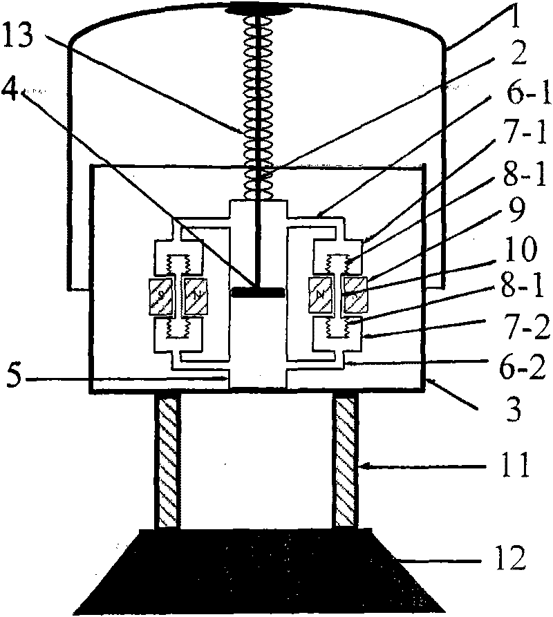
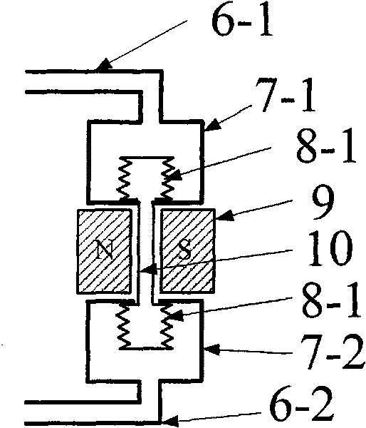
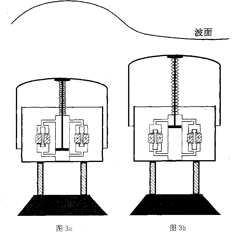
[0021] figure 1 It is a schematic diagram of a specific embodiment of the present invention. Such as figure 1 As shown, the specific embodiment of the present invention mainly consists of an outer cylinder 1, a piston rod 2, a return spring 13, an inner cylinder 3, a piston 4, a main hydraulic cylinder 5, a rigid support 11, a base 12, and 16 hydraulic units and 16 LMMHDs Generator composition. The outer cylinder 1 and the inner cylinder 3 are coaxial and set in the vertical direction. The outer cylinder 1 and the inner cylinder 3 form a buoy, which is filled with compressed air and completely submerged below the sea surface; the inner cylinder 3 is fixed on the rigid support 11, and the inner cylinder 3 The base 12 is fixed on the seabed through the rigid support 11 and the base 12; the whole device is vertically arranged in seawater severa...


PUM


Abstract

A submerged generating device directly utilizing liquid metal magnetic fluid wave energy consists of an outer barrel (1), a piston rod (2), a return spring (13), an inner barrel (3), a piston (4), a main hydraulic cylinder (5), a rigid support (11), a base (12), n (n=1, 2, 3...) hydraulic units and n (n=1, 2, 3...) liquid metal magnetic fluid generators. The outer barrel (1) is coaxial with an inner barrel (3), the inner barrel (3) is fixed on the rigid support (11), the inner barrel (3) is fixedly connected with the rigid support (11) and the base (12), the base (12) is fixed on a seabed, the outer barrel (3) is connected with the piston (4) which is coaxially arranged in the main hydraulic cylinder (5) via the piston rod (2) which is arranged along an central axis of the inner barrel (3), the return spring (13) is sleeved outside the piston rod (2), the main hydraulic cylinder (5), the n hydraulic units and the n liquid metal magnetic fluid generators are arranged in the inner barrel (3), and the whole device is vertically arranged below the sea level.

Description

technical field [0001] The invention relates to a liquid metal magnetic fluid wave energy direct power generation device, in particular to a direct drive liquid metal magnetic fluid wave energy power generation device submerged at a certain depth below the sea surface. technical background [0002] Wave energy is a kind of energy that exists in the form of large force (several tons to tens of tons) and low speed (0.5-2m / s). It is the energy with the highest grade and the largest proportion in ocean energy. With the gradual reduction of mineral energy in the world and the increasing environmental pollution, wave energy is undoubtedly one of the preferred clean and renewable energy sources, and wave energy power generation is at the top of the development and utilization of marine renewable energy. [0003] Traditional wave power generation uses a high-speed, low-torque rotating generator. To couple it with low-speed, high-force wave motion, a series of mechanical devices for ...

Claims


Application Information

Patent Timeline
Patent Type & Authority Applications(China)
IPC IPC(8): F03B13/16H02K7/18H02K44/08
CPCY02E10/38Y02E10/30
Inventor 彭燕赵凌志沙次文李然许玉玉刘保林李建
Owner INST OF ELECTRICAL ENG CHINESE ACAD OF SCI
Why Eureka
Try Eureka