Waste heat recovery system of exhaust gas of metallurgical converter

A waste heat recovery system and gas release technology, which is applied in the field of waste heat recovery system for metallurgical converters to release gas, to achieve the effects of increasing the discharge height, smooth flue gas circulation, and reducing pollution

Inactive Publication Date: 2010-04-14
无锡市东方环境工程设计研究所有限公司
View PDF0 Cites 17 Cited by
  • Summary
  • Abstract
  • Description
  • Claims
  • Application Information

AI Technical Summary

Problems solved by technology

[0003] The invention is mainly aimed at recovering the dissipated energy when the converter gas content is lower than 30% and cannot enter the gas holder

Method used


Image

  • Waste heat recovery system of exhaust gas of metallurgical converter
  • Waste heat recovery system of exhaust gas of metallurgical converter

Examples


Embodiment 1

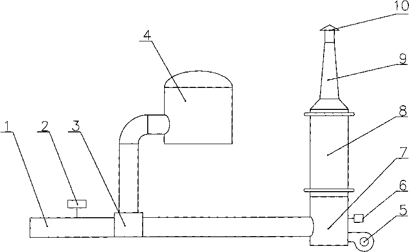
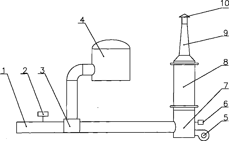
[0015] A 40-ton converter, when the CO concentration is lower than 30%, is switched into the combustion chamber 7 by the three-way valve 3, after the supplementary air combustion, high-temperature flue gas is produced, and the flue gas volume is 48000Nm 3 / h, the flue gas temperature is 1200℃. The combustion chamber 7 has a diameter of 3.5m and a height of 5.5m. A membrane wall is provided in the combustion chamber 7 as a radiant heat exchange surface to absorb the radiant heat of CO combustion and reduce the temperature of the furnace wall of the combustion chamber 7 at the same time. The flue gas enters the waste heat recovery boiler 8 after radiating heat exchange through the combustion chamber 7. The waste heat recovery boiler 8 has a diameter of 3.5m and a height of 12m. After the flue gas passes through the waste heat recovery boiler 8, the temperature drops to 200°C, and is discharged into the atmosphere through the exhaust chimney 9, and at the same time, 0.6Mpa saturate...


PUM


Abstract

The invention discloses a waste heat recovery system of exhaust gas of a metallurgical converter, which comprises a CO detector, a three-way valve, a burning chamber, a burner and an exhaust smokestack and is characterized in that a waste heat recovery boiler is arranged between the exhaust smokestack and the burning chamber. In the system, when the gas concentration of the converter is lower than 30% and the gas cannot enter a gas cabinet, exhaust energy is recovered; by arranging the waste heat recovery boiler on the bottom of an exhaust chimney as well as heating softened water by heat generated by burning the gas, the heat valve of the gas of the converter is fully recovered, and the generated saturated steam can be used for production and life.

Description

Technical field [0001] The invention relates to a recovery system for smelting coal gas, in particular to a waste heat recovery system for gas released from a metallurgical converter. Background technique [0002] The converter produces a large amount of high-concentration CO-containing gas during the blowing process, the temperature of which is 1400-1600°C, and the gas content reaches 60-85%. After cooling and dust removal, it enters the gas tank for production use. However, in the pre-combustion and post-combustion periods, the CO content of the converter is low, the volume content is less than 30%, and the duration is about 10 minutes. During this period, the gas cannot enter the gas tank because the CO content cannot reach the recoverable condition. It is usually discharged through a switching valve. In the discharge process, in order to prevent environmental pollution, CO is ignited at the end of the chimney to form a torch. The large amount of heat generated when the gas i...

Claims


Application Information

Patent Timeline
Patent Type & Authority Applications(China)
IPC IPC(8): F27D17/00F22B1/18C21C5/40
CPCY02P10/25
Inventor 张鹏周志东
Owner 无锡市东方环境工程设计研究所有限公司
Why Eureka
Try Eureka