Organic electroluminescence device
An electroluminescent device and luminescence technology, which is applied in the direction of electric solid-state devices, electrical components, organic dyes, etc., can solve problems such as poor chromaticity, poor color stability, and low blue light luminous efficiency, and achieve an increase in working life , The effect of compound area expansion
- Summary
- Abstract
- Description
- Claims
- Application Information
AI Technical Summary
Problems solved by technology
Method used
Image

Examples
Embodiment 1
[0046] Embodiment 1 is a kind of blue OLED, and device structure is as follows:
[0047] ITO / NPB / BH 1 :NPB:BD 1 / BH 1 :BD 2 / Alq 3 / LiF / Al
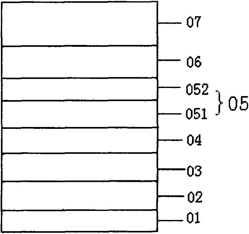
[0048] like figure 1 As shown, the light-emitting layer 05 is a composite blue light-emitting layer, including blue light-emitting layer 1 (051) and blue light-emitting layer 2 (052). The blue light-emitting layer 1 is formed by mixing two host materials and doping blue light dyes, one of which is an electron-transporting material BH 1 , the other main body is the material N, N'-diphenyl N, N'-(1-naphthyl)-1,1'-biphenyl-4,4'-diamine (hereinafter referred to as NPB ), the doped blue light dye is shown in formula (10) (referred to as BD 1 ):
[0049]
[0050] The blue light-emitting layer 2 is formed by doping a blue light dye with a single host material, and the host is BH with electron transport properties. 1 , the doped blue light dye is shown in formula (5) (referred to as BD 2 ):
[0051]
[0052] The method for prepa...
Embodiment 2~ Embodiment 4
[0060] The device structures and preparation methods of Examples 2 to 4 are basically the same as those of Examples, the difference being that the weight percentages of blue light dye doping in the blue light-emitting layer 2 of Examples 2 to 4 are respectively 3%, 6%, the device performance of 10% above-mentioned embodiment 1~4 is as shown in table 2:
[0061] Table 2
[0062]
[0063] As can be seen from the device performance data in the foregoing embodiments, BD 1 and BD 2 Two kinds of dyes ensure the device has high luminous efficiency. At the same time, through the sky blue dye BD 2 As the doping concentration increases, the color coordinates of the device change in the range of (0.14, 0.22) to (0.15, 0.29), and the color appears blue from deep to light. Therefore, by adjusting the doping concentration of one of the dyes, the chromaticity of the device can be adjusted more easily.
Embodiment 5
[0065] Embodiment 5 is a white OLED with double light-emitting centers, and the device structure is as follows:
[0066] ITO / NPB / NPB:rubrene / BH 1 :NPB:BD 1 / BH 1 :BD 2 / Alq 3 / LiF / Al
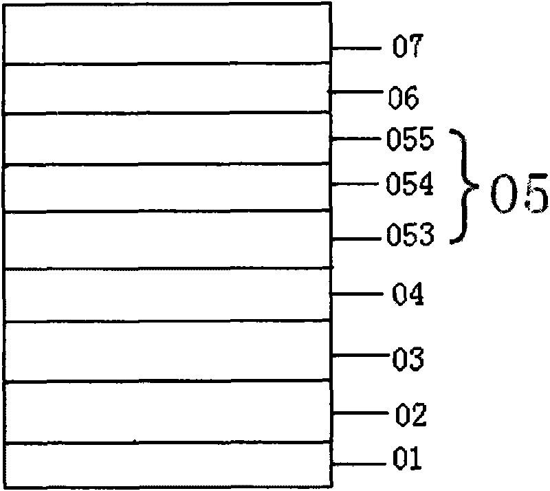
[0067] like figure 2 As shown, the light-emitting layer 05 respectively includes a yellow light-emitting layer 053, a blue light-emitting layer 1 (054), and a blue light-emitting layer 2 (055), wherein the yellow light-emitting layer is doped with a yellow dye 5 using NPB, a host material with hole transport properties, 6,11,12-Tetraphenyltetracene (rubrene for short).
[0068] The blue light-emitting layer 1 is formed by mixing two host materials and doping a blue dye, one of which is an electron-transporting material BH 1 , the other host is NPB, and the doped blue dye is shown in formula (10) (referred to as BD 1 ), BD 1 in BH 1 The weight percentage of doping in is 5%:
[0069]
[0070] The blue light-emitting layer 2 is formed by doping a blue dye with a single host material,...
PUM
 Abstract
Description
Claims
Application Information
 - R&D
- Intellectual Property
- Life Sciences
- Materials
- Tech Scout
- Unparalleled Data Quality
- Higher Quality Content
- 60% Fewer Hallucinations
Browse by: Latest US Patents, China's latest patents, Technical Efficacy Thesaurus, Application Domain, Technology Topic, Popular Technical Reports.
© 2025 PatSnap. All rights reserved.Legal|Privacy policy|Modern Slavery Act Transparency Statement|Sitemap|About US| Contact US: help@patsnap.com