Regenerative dehumidification heat exchange device

A heat exchanger, regenerative technology, applied in household heating, heating methods, lighting and heating equipment, etc., can solve problems such as unfavorable desiccant dehumidification/regeneration, reduced operating efficiency, waste of energy, etc., to improve indoor air. The effect of quality, low equipment investment cost and simple production process

Active Publication Date: 2010-04-28
SHANGHAI JIAO TONG UNIV
View PDF0 Cites 27 Cited by
  • Summary
  • Abstract
  • Description
  • Claims
  • Application Information

AI Technical Summary

Problems solved by technology

However, refrigeration dehumidification also has the following disadvantages: (1) limited by the temperature of the cooling medium, cooling and dehumidification cannot provide low or ultra-low dew point air supply conditions; (2) temperature and humidity cannot be controlled separately. Humidity often needs to treat the air to a lower temperature first, and then heat the air to meet the temperature and humidity requirements of the air supply, which wastes more energy; (3) When the dew point required by the air supply is lower than 4°C, Due to the frosting problem of the evaporator of the conventional refrigeration system, the operating efficiency of the equipment will be greatly reduced and the energy consumption will be greatly increased
However, drying and dehumidification also have disadvantages: in the dehu...

Method used


Image

  • Regenerative dehumidification heat exchange device
  • Regenerative dehumidification heat exchange device
  • Regenerative dehumidification heat exchange device

Examples


Embodiment 1

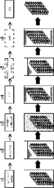
[0042] The manufacturing method of the regenerative dehumidification heat exchanger involved in this embodiment is as follows: figure 1 , 3 Shown:

[0043] In the cleaning and drying process (S1), the tube-fin heat exchanger 1 with a specification of 202×168×25mm and a fin spacing of 1mm and the tube-fin heat exchanger 2 with a specification of 202×168×25mm and a fin spacing of 0.5mm Clean it and dry it with an electric constant temperature blast drying oven at a drying temperature of 40°C ± 0.2°C. After drying, the masses of heat exchanger 1 and heat exchanger 2 are 483.58g and 513.78g, respectively. After the dried tube-fin heat exchanger is placed in the room to cool naturally, in the adhesive coating process (S2), it is coated with adhesive, and after coating, the excess adhesive is removed with a compressed air machine In order not to block the heat exchange air passage, a uniform thin layer of adhesive with a thickness of about 0.1 mm is formed on the surface of the tu...

Embodiment 2

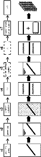
[0048] The manufacturing method of the regenerative dehumidification heat exchanger involved in this embodiment is as follows: figure 2 .3 shows:

[0049] In the cleaning and drying process (S1), the metal sheet with a thickness of about 0.2mm and a mass of 1.00g is cleaned and dried in an electric constant temperature blast drying oven at a drying temperature of 40°C±0.2°C. Put the dried tube-fin heat exchanger in the room to cool naturally, and then carry out the adhesive coating process (S2), and then use a compressed air machine to remove the excess adhesive to form a uniform layer on the surface of the metal sheet. A thin layer of adhesive with a thickness of approximately 0.1 mm. Expose the metal sheet after the process of coating the adhesive (S2) to the air for about 10 minutes to evaporate part of the moisture in the adhesive, and then carry out the process of coating the solid desiccant powder (S3), and the silica gel solid powder Evenly sprinkled on the adhesive,...

Embodiment 3

[0055] The regenerative dehumidification heat exchanger involved in this embodiment has a specific structure such as Figure 4 As shown, the cooling system is a cooling tower system 1, and the heating system is a solar collector system 2.

[0056] This embodiment includes: a cooling tower system 1, a solar collector system 2, and a dehumidification and heat exchange system 3, wherein the dehumidification and heat exchange system 3 is further divided into a regeneration area 33 and a treatment area 32, and the three systems are connected by water pipes.

[0057] The cooling tower system 1 includes: a cooling tower 4 , a water pump 5 , a sprinkler 6 , a water pump 7 , a valve 8 , and a cold water tank 9 . The connection relationship is: one end of the water pump 5 is connected to the cold water tank 9 through a water pipe, the other end of the water pump 5 is connected to the cooling tower 4, the other end of the cooling tower 4 is connected to the valve 8, and the other end of ...


PUM


Abstract

The invention relates to a regenerative dehumidification heat exchange device belonging to the technical field of refrigeration. The dehumidification heat exchange device comprises a cooling system, a heating system and a dehumidification heat exchange system, wherein the dehumidification heat exchange system is divided into a processing zone and a regeneration zone; the three systems are connected through pipelines; the processing zone of the dehumidification heat exchange system is connected with the cooling system through a pipeline, and the regeneration zone of the dehumidification heat exchange system is connected with the heating system through a pipeline; and continuous dehumidification can be realized by switching between the dehumidification zone and the regeneration zone. In the invention, a drying agent is coated on the heat exchange device or metal sheets to obtain the regenerative dehumidification heat exchange device; the dehumidification heat exchange device adopts cooling water and hot water in an inner pipe to cool and heat the drying agent, wherein the convection heat exchange coefficient of water is greatly higher than the convection heat exchange coefficient of gas, thereby being favorable to dehumidification and regeneration of the drying agent; the device is more compact; and the comprehensive performance of the dehumidification heat exchange device can be improved.

Description

[0001] The present invention is based on the patent application number: 200910045066.1, the patent application name is: "regenerative dehumidification heat exchanger and its manufacturing method", the patent applicant is: Shanghai Jiaotong University, and the patent application date is: January 8, 2009. Divisional application. technical field [0002] The invention relates to a heat exchanger in the technical field of refrigeration, in particular to a regenerative dehumidification heat exchanger. Background technique [0003] Air dehumidification technology mainly includes several methods of freezing dehumidification, compressed air dehumidification and desiccant dehumidification. The compressed air dehumidification method needs to compress the air, increase the partial pressure of water vapor, and separate the water vapor to obtain dry air after condensation. This method is effective for small air volumes, but it is not suitable for large air volumes. Freezing dehumidifica...

Claims


Application Information

Patent Timeline
IPC IPC(8): F24F3/14B05D5/00
Inventor 代彦军彭作战腊栋王如竹李勇
Owner SHANGHAI JIAO TONG UNIV
Why Eureka
Try Eureka