Device and method for processing waste firedamp liquid

A treatment device and biogas slurry technology, applied in fertilization equipment, chemical instruments and methods, biological water/sewage treatment, etc., can solve the problems of high cost of waste biogas slurry, secondary pollution, etc., achieve less land occupation and zero discharge , The effect of convenient construction

Inactive Publication Date: 2010-05-05
INST OF MICROBIOLOGY HEILONGJIANG ACADEMY OF SCI
View PDF0 Cites 12 Cited by
  • Summary
  • Abstract
  • Description
  • Claims
  • Application Information

AI Technical Summary

Problems solved by technology

[0003] In order to solve the problems of high cost of purifying waste biogas liquor and easy to cause secondary pollution in the exi

Method used


Image

  • Device and method for processing waste firedamp liquid
  • Device and method for processing waste firedamp liquid
  • Device and method for processing waste firedamp liquid

Examples


specific Embodiment approach 1

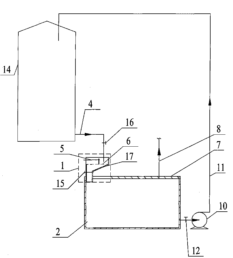
[0009] Specific implementation manner one: such as figure 1 As shown, the waste biogas slurry treatment device in this embodiment includes a sewage pump 10, an outlet pipe 11, a waste biogas slurry outflow pipe 4, a separation device 1, a fermentation tank 2 and a cover plate 7. The separation device 1 consists of a funnel. A shaped shell 17, a slag cleaner 5 and a filter screen 6. The slag cleaner 5 and the filter screen 6 are arranged in the upper cylindrical cavity of the funnel-shaped shell 17 from top to bottom, and the cover plate 7 is arranged in the fermentation tank 2. The upper end surface of the biogas fermentation tank 14 is hermetically connected with the fermentation tank 2; the separation device 1 is arranged below the biogas fermentation tank 14. The lower end side wall of the biogas fermentation tank 14 communicates with the separation device 1 through the waste biogas liquid outflow pipe 4, and the funnel-shaped shell 17 The lower end is installed on the cover ...

specific Embodiment approach 2

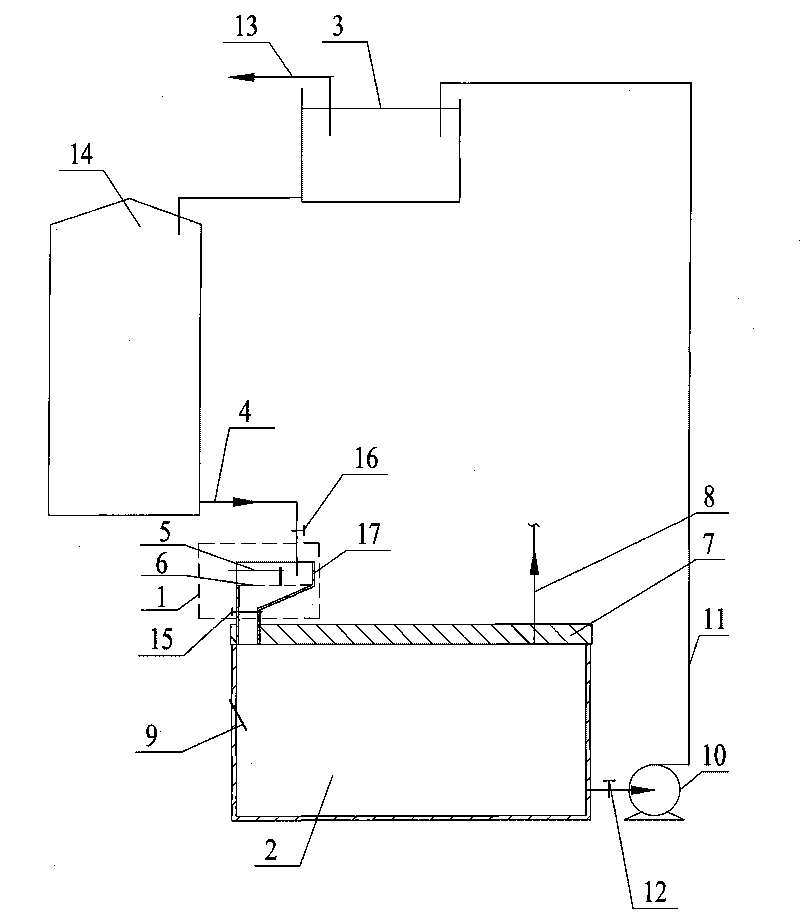
[0012] Specific implementation manner two: such as figure 2 As shown, the processing device of this embodiment further includes a batching tank 3, and the other end of the outlet pipe 11 is in communication with the upper end of the biogas fermentation tank 14 through the batching tank 3. The batching tank 3 is also provided with a feed pipe 13. The other components and connection relationships are the same as in the first embodiment.

[0013] The batching tank 3 in this embodiment can be constructed with a brick-concrete structure, with anti-corrosion treatment inside and waterproof protection outside, which has good corrosion resistance and reduces production costs.

[0014] Specific implementation manner three: such as figure 1 with 2 As shown, the processing device of this embodiment further includes a temperature sensor 9 which is arranged on the side wall of the fermentation tank 2 and the measuring end of the temperature sensor 9 is located in the fermentation tank 2. Othe...

specific Embodiment approach 8

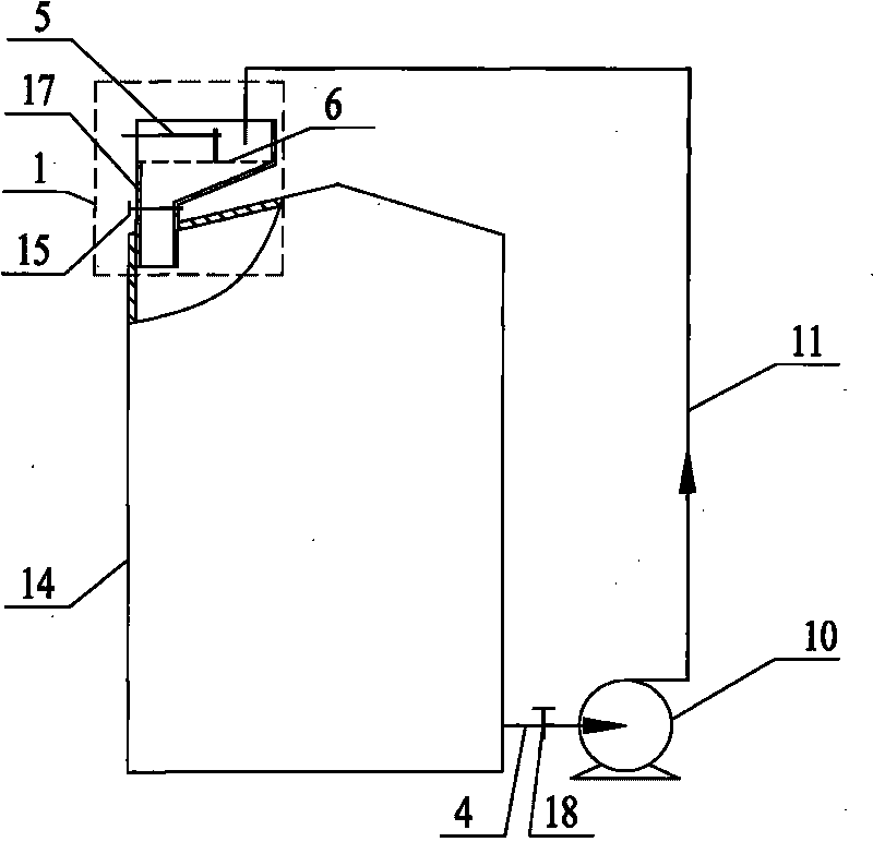
[0020] Specific implementation manner eight: such as image 3 As shown, the processing device of this embodiment further includes a separation device control valve 15 and a first waste biogas slurry flow control valve 18. The separation device control valve 15 is arranged on the cone of the funnel-shaped shell 17 and is located in the fermentation tank. 2 outside; the first waste biogas slurry flow control valve 18 is set on the waste biogas slurry outflow pipe 4. The other composition and connection relationship are the same as in the seventh embodiment.


PUM


Abstract

The invention relates to a device and a method for processing waste firedamp liquid, belonging to the field of sewage treatment. The invention solves the problems of high cost of purifying the waste firedamp liquid and easy secondary pollution of the traditional processes for treating the waste firedamp liquid. A separation device is arranged under a firedamp fermentation cylinder, the side wall at the lower end of the firedamp fermentation cylinder is communicated with the separation device by a waste firedamp liquid outlet pipe, a liquid outlet on the side wall of a fermentation tank is communicated with one end of an outlet pipe by a sewage pump, and the other end of the outlet pipe is communicated with the upper end of the firedamp fermentation cylinder. The method comprises the following steps: after filtrated, residuals generated after firedamp fermentation is fermented and then completely flows back to be used for fermenting the firedamp, thereby finishing treatment of the waste firedamp liquid. The device for processing the waste firedamp liquid has the advantages of simple structure, low manufacturing cost, little ground occupation, high strength and convenient construction; the method for processing the waste firedamp liquid by the device is simple and convenient to operate and reduces the purification cost, and the generated firedamp is used as energy, which purifies the environment.

Description

Technical field [0001] The invention belongs to the field of sewage treatment, and specifically relates to a treatment device and a treatment method for waste biogas slurry. Background technique [0002] Biogas is a renewable clean energy. The development of biogas is an important part of China's energy strategy. It is of great practical significance for increasing the supply of high-quality energy and alleviating the country's energy pressure. With the large-scale application of biogas, the treatment of waste biogas slurry in the residue (composed of waste biogas residue and waste biogas slurry) after fermentation has become the focus of attention. The existing process for processing waste biogas slurry is to purify and then discharge the generated sewage. However, the cost of purifying the waste biogas slurry is very high and it is easy to cause secondary pollution. Summary of the invention [0003] In order to solve the problems of high cost of purifying waste biogas slurry an...

Claims


Application Information

Patent Timeline
IPC IPC(8): C02F9/14C02F3/34C05F5/00
CPCY02E50/343Y02A40/20Y02E50/30Y02W30/40
Inventor 谷军沙长青张小彦原韬
Owner INST OF MICROBIOLOGY HEILONGJIANG ACADEMY OF SCI
Why Eureka
Try Eureka