Self-adsorption ejector desulfurizing tower and manufacturing process thereof

A technology of injector and desulfurization tower, which is applied in the field of self-priming ejector desulfurization tower and its technology, can solve the problems of short service time, low corrosion resistance, and increased operating costs

Inactive Publication Date: 2010-05-19
林吉萍
View PDF0 Cites 15 Cited by
  • Summary
  • Abstract
  • Description
  • Claims
  • Application Information

AI Technical Summary

Problems solved by technology

[0004] First, the structure is complex, and the whole desulfurization system has a large number of large-scale equipment, such as the desulfurization tower with a diameter of φ5000mm or more, the regeneration tower with a diameter of φ4000mm or more, a height of 40m or more, and some large-diameter tanks, etc.
The construction area is large, and the pipeline layout is wide and long, which increases the investment cost of equipment
[0005] Second, the regeneration tower with complex process uses compressed air to oxidize and regenerate the desulfurized rich liquid, so it is necessary to build a high-pressure air station and

Method used


Image

  • Self-adsorption ejector desulfurizing tower and manufacturing process thereof
  • Self-adsorption ejector desulfurizing tower and manufacturing process thereof
  • Self-adsorption ejector desulfurizing tower and manufacturing process thereof

Examples


Embodiment

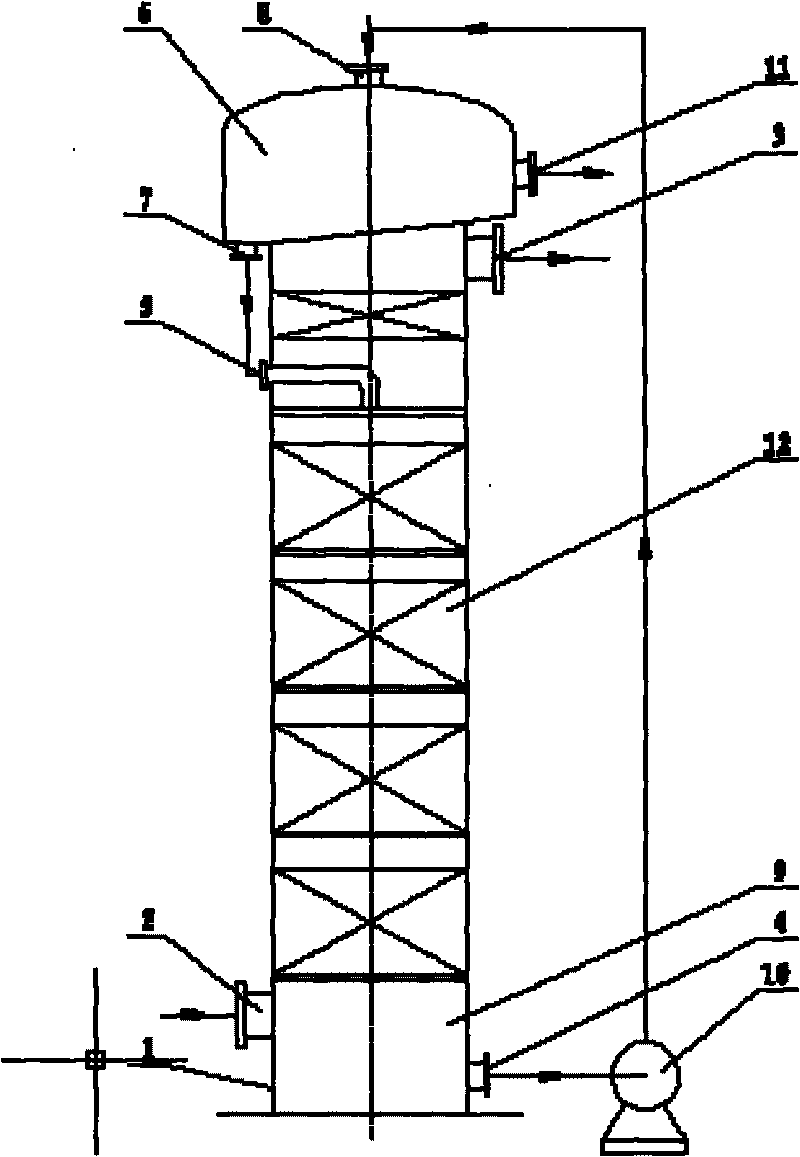
[0014] Attached below figure 2 The present invention is further described.

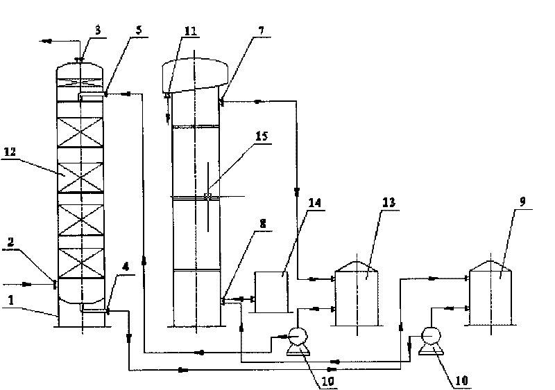
[0015] The bottom of the lower section of the desulfurization tower 1 is a rich liquid tank 9, which is provided with a rich liquid outlet 4 and a gas inlet 2, a packing 12 and a liquid inlet distributor are installed in the middle section of the tower, and a gas outlet 3 is opened on the side of the desulfurization tower cylinder in the upper section of the tower , a set of self-priming oxidation regeneration injector 6 is installed on the top of the tower, and a solution circulation pipeline is installed outside the tower body. A solution circulation pump 10 makes the solution flow inside and outside the tower through the rich solution inlet 8, the lean solution outlet 7, and the lean solution inlet 5. cycle. The process is that the crude gas from the cold drum electric capture section enters from the lower nozzle 2 of the desulfurization tower 1 into the countercurrent contact washing with the de...


PUM


Abstract

The invention discloses a self-adsorption ejector desulfurizing tower, which optimally designs and integrates four pieces of main equipment, namely a desulfurizing tower 1, a regenerating tower 15, a pregnant solution tank 9 and a barren solution tank 13, in a traditional coke oven gas desulfurizing system, into a whole, without increasing the diameter and the height of the tower, eliminates the regenerating tower, the barren solution tank and the barren solution pump, designs the skirt support part at the bottom part of the desulfurizing tower into the pregnant solution tank so as to store a desulfurizing circulation fluid, arranges a set of self-adsorption oxidizing and regenerating ejector 6 at the top of the desulfurizing tower 1, and uses the ejector 6 to suck air so as to oxidize and regenerate a desulfurized barren solution, wherein sulfur foams generated after regeneration automatically flow into a sulfur foam tank; the generated desulfurized barren solution is used for spraying a raw gas reversely flowing upwards from the lower part of the tower directly from the top of the tower through a liquid spreader so as to wash and absorb sulfureted hydrogen contained in a raw gas; the raw gas is changed into a pregnant solution which flows into the pregnant solution tank at the bottom of the desulfurizing tower; and a solution circulating pump pumps the pregnant solution into the ejector at the top of the tower to be oxidized and regenerated. The circulating operation realizes the function of using a piece of equipment to finish the work which is finished by four pieces of equipment. The self-adsorption ejector desulfurizing tower decreases the investment of the equipment, simplifies the production process, reduces the energy consumption and improves the desulfurizing efficiency.

Description

Technical field: [0001] The invention relates to a method for removing H contained in coke oven gas 2 The equipment and process of S, HCN and other substances, specifically a desulfurization tower and process for oxidizing and regenerating the desulfurization liquid by using a self-priming injector. Background technique: [0002] The traditional desulfurization tower and its process are relatively complicated, mainly composed of a desulfurization tower 1, a regeneration tower 15, a lean liquid tank 13, and a rich liquid tank 9. The desulfurization liquid sprayed from the lower part of tower 1 and the top of the tower contact with countercurrent to wash and absorb hydrogen sulfide in the gas, and the gas from which hydrogen sulfide is removed is sent to the next section from the nozzle 3 at the top of the tower, and the desulfurization liquid flowing out from the nozzle 4 at the lower part of the desulfurization tower The solution (also called rich solution at this time) ent...

Claims


Application Information

Patent Timeline
IPC IPC(8): C10K1/08C01B17/05
Inventor 林吉萍
Owner 林吉萍
Why Eureka
Try Eureka