
Dry gas sealing device for technical screw compressor and application system thereof

A screw compressor, dry gas sealing technology, applied in the direction of engine seals, mechanical equipment, engine components, etc., can solve problems such as unfavorable lubricating oil system safe operation, large heat generation on the sealing end face, pollution of lubricating oil, etc., to achieve low friction coefficient, operational safety, and the effect of preventing gas leakage

Inactive Publication Date: 2010-05-26
NO 711 RES INST CHINA SHIPPING HEAVY IND GRP
View PDF0 Cites 32 Cited by
  • Summary
  • Abstract
  • Description
  • Claims
  • Application Information

AI Technical Summary

Problems solved by technology

Process screw compressors are used in high-pressure, high-speed applications. If oil film mechanical seals are selected, in order to ensure that the pressure of the lubricating oil in the sealing chamber is higher than the pressure of the medium gas, the outlet of the oil pump is required to provide a high lubricating oil pressure, which is not conducive to the maintenance of the lubricating oil system. Safe operation, and under high pressure and high speed, the sealing end face will generate a lot of heat and be easily damaged; if a carbon ring seal is selected, the process gas and carried moisture will easily leak to the lubricating oil tank through the gap between the carbon ring and the rotor to pollute the lubricating oil

Method used


Image

  • Dry gas sealing device for technical screw compressor and application system thereof
  • Dry gas sealing device for technical screw compressor and application system thereof
  • Dry gas sealing device for technical screw compressor and application system thereof

Examples


Embodiment Construction

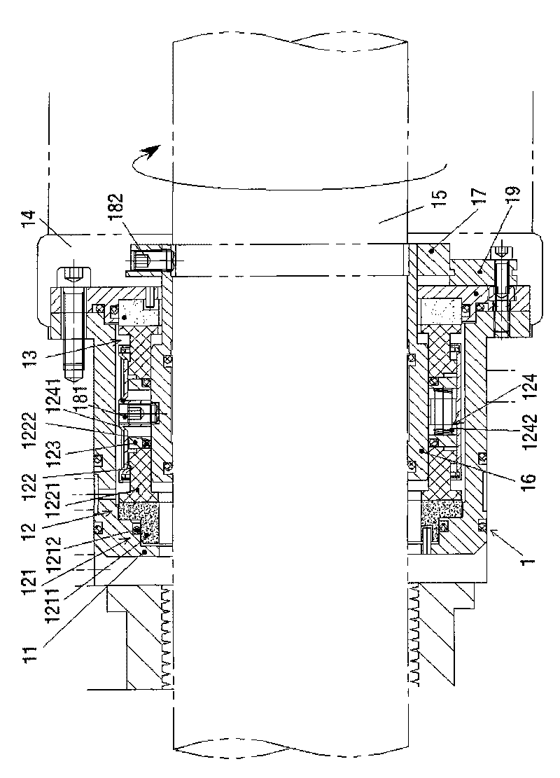
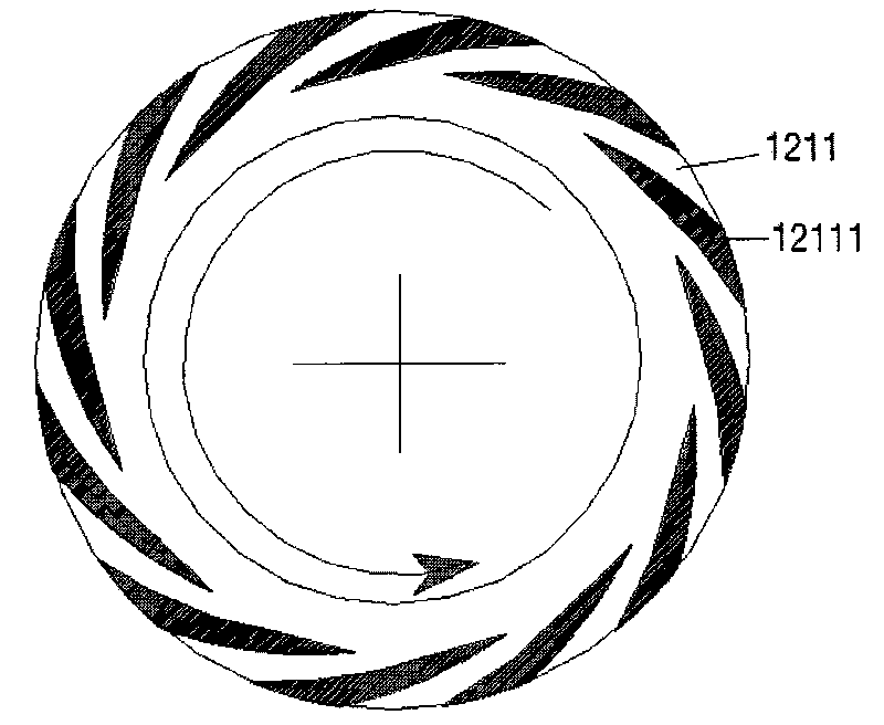
[0027] see figure 1 , figure 1 It is a structural schematic diagram of the dry gas sealing device used in the process screw compressor of the present invention. The present invention is a dry gas sealing device 1 for process screw compressors, comprising a gland 11 and two sets of single sealing mechanisms 12 and 13 with the same structure relatively arranged in the gland, the glands are filled with Gases including nitrogen. Since the two sets of single-sealing mechanisms have the same structure, the single-sealing mechanism 12 is taken as an example for detailed description. The single seal 12 includes a stationary ring assembly 121 , a moving ring assembly 122 , a push ring 123 , and a spring assembly 124 arranged in sequence. The static ring assembly 121 includes a static ring and 1211 a static ring sealing ring 1212, the moving ring assembly 122 includes a moving ring 1221 and a moving ring sealing ring 1222, and the spring assembly includes a spring seat 1241 and A sp...


PUM


Abstract

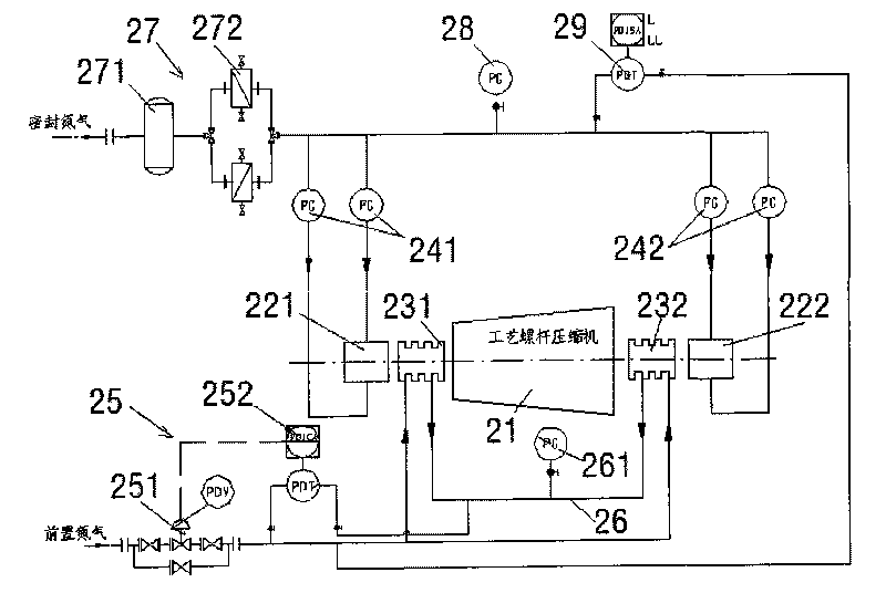
The invention discloses a dry gas sealing device for a technical screw compressor and an application system thereof. The dry gas sealing device is characterized by comprising two sets of single sealing mechanisms with the same structure, wherein each set of single sealing mechanism comprises a static ring component, a moving ring component, a push ring and a spring component, wherein the static ring component is fixedly connected with a gland, and the moving ring component, the push ring and the spring component are fixedly connected with a shaft sleeve. The application system comprises a technical screw compressor, two dry gas sealing devices, two labyrinth sealing devices, two groups of gas flowmeters of sealed gas, a front-end gas input device and a sealed gas input device, wherein the two dry gas sealing devices and the two labyrinth sealing devices are symmetrically arranged at two ends of the shaft of the technical screw compressor. The invention also discloses an application method of the application system.The dry gas sealing device for the technical screw compressor of the invention has self adaptation and non-contact characteristics, can ensure reliable operation of dry gas sealing by matching the combined application system which has balancing cavity pressure relief, labyrinth seal obstruction, front-end nitrogen protection and dry gas sealing, and is especially suitable for high-pressure technical screw compressors with high rotary speed.

Description

technical field [0001] The invention relates to a dry gas sealing device for process screw compressors applied in the field of petrochemical industry and an application system thereof. Background technique [0002] For process screw compressors used in the petrochemical industry, the compression chamber must be separated from the bearing, otherwise the acid gas in the process gas will enter the bearing lubricating oil and cause oil deterioration, damage bearings and synchronous gears and other components, so the compression chamber and Seals with high performance and reliability must be used between bearings to block process gas and lubricating oil. Process screw compressors are used in high-pressure, high-speed applications. If oil film mechanical seals are selected, in order to ensure that the pressure of the lubricating oil in the sealing chamber is higher than the pressure of the medium gas, the outlet of the oil pump is required to provide a high lubricating oil pressur...

Claims


Application Information

Patent Timeline
IPC IPC(8): F16J15/16F16J15/40F16J15/447F04C18/16
Inventor 蔡宏朱立伟顾小欢徐明照汪东
Owner NO 711 RES INST CHINA SHIPPING HEAVY IND GRP
Learn More