Real-time online optical fiber oxygen sensor

An oxygen sensor and optical fiber sensing probe technology, applied in fluorescence/phosphorescence, material excitation analysis, etc., can solve the problems of easy poisoning of electrodes and oxygen consumption, and achieve low cost, rapid response, good stability and repeatability Effect

Inactive Publication Date: 2010-05-26
DALIAN INST OF CHEM PHYSICS CHINESE ACAD OF SCI
View PDF0 Cites 12 Cited by
  • Summary
  • Abstract
  • Description
  • Claims
  • Application Information

AI Technical Summary

Problems solved by technology

This method can realize continuous measurement on site, but it needs to consume oxyge

Method used


Image

  • Real-time online optical fiber oxygen sensor
  • Real-time online optical fiber oxygen sensor
  • Real-time online optical fiber oxygen sensor

Examples


Embodiment 1

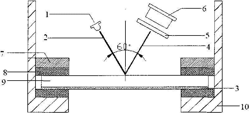
[0020] Such as figure 1 As shown, a real-time on-line optical fiber oxygen sensor of the present invention is mainly composed of a high-power light-emitting diode (excitation light source 1), an excitation optical fiber 2, an oxygen fluorescence sensitive film 3, a receiving optical fiber 4, an optical filter 5, and a signal receiving And processing system 6 composition. In addition, there are fastening nut 7, O ring 8, carrier glass piece 9, cell body 10 of flow cell, sample inlet 11, sample outlet 12, detection chamber 13 and other accessories.

[0021] The optical fiber sensing probe is composed of a single excitation optical fiber 2 and a single receiving optical fiber 4 whose top ends are in contact with each other. The contact ends of the excitation optical fiber 2 and the receiving optical fiber 4 form an angle of 60 degrees with each other.

[0022] A probe fixing sleeve assembly is sleeved on the outside of the excitation optical fiber 2 and the receiving optical fib...

Embodiment 2

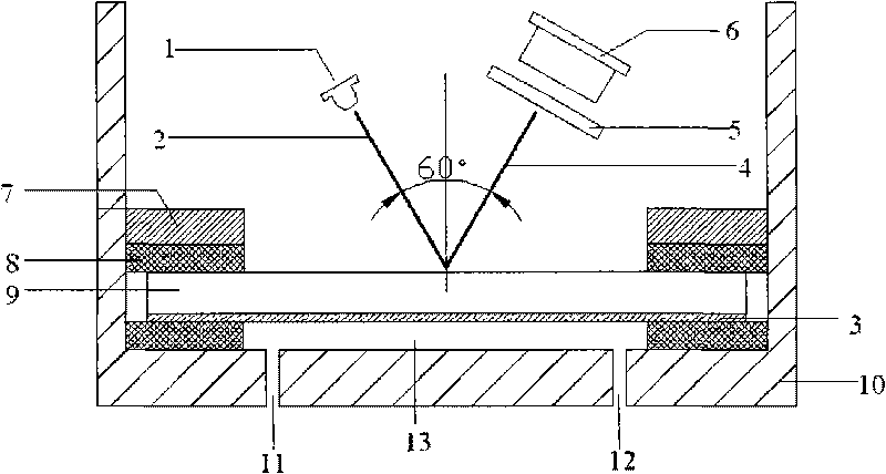
[0036] The difference from Example 1 is that, as figure 2 Shown:

[0037] The lower end of the U-shaped barrel-shaped flow cell body 11 is provided with a sample inlet (11) and a sample outlet (12), and a detection chamber 13 is formed on the oxygen fluorescent sensitive membrane 3 and the bottom surface of the flow cell body (10). .


PUM

PropertyMeasurementUnit
Angleaaaaaaaaaa

Abstract

The invention relates to a real-time online optical fiber oxygen sensor. A high power light-emitting diode or pulse lamp is adopted as the excitation light source. The excitation light is transmitted by an exciting optical fiber to irradiate an oxygen fluorescence sensing membrane, and the generated fluorescence is collected by a launching optical fiber after passing through an optical filter and is transmitted to an optoelectronic conversion device to be detected. In a probe of the optical fiber oxygen sensor, the exciting optical fiber and the launching optical fiber forms an angle of 50-70 degrees, thus effectively reducing interference of media. The maximal fluorescence receiving efficiency can be obtained near the angle of 60 degrees. The oxygen fluorescence sensing membrane is placed in the sensor and can continuously detect the oxygen content in the gas and the dissolved oxygen in the water on line in real time. The sensor has the advantages of long service life, wide measurement range, high sensitivity, good stability and repeatability, easy miniaturization and the like.

Description

technical field [0001] The invention relates to an optical fiber oxygen sensor, in particular to an optical fiber oxygen sensor used for real-time in-body measurement of oxygen content in gas or dissolved oxygen in water. Background technique [0002] The determination of the oxygen content in the gaseous state and the dissolved oxygen concentration in water is very important in the fields of industry, medicine and the environment. The traditional oxygen measurement method is the amperometric method (that is, the Clark oxygen electrode method). The oxygen electrode method is mainly detected by the tiny current generated by the consumption of oxygen by the analyte in the electrochemical reaction. This method can realize continuous measurement on site, but it needs to consume oxygen, so it can only measure oxygen in water, and the electrodes used are easily poisoned. The optical oxygen sensor was gradually developed in the mid-1980s. It mainly uses the principle of oxygen fl...

Claims


Application Information

Patent Timeline
IPC IPC(8): G01N21/64
Inventor 熊艳关亚风宋翠红徐静陈士恒
Owner DALIAN INST OF CHEM PHYSICS CHINESE ACAD OF SCI
Why Eureka
Try Eureka