Float level gauge for high temperature and high pressure or high pressure low density medium

A liquid level gauge and float type technology, which is applied in the field of liquid level measurement, can solve the problems of increasing the diameter of the float chamber, many parts in the float chamber, and increasing the manufacturing cost, so as to improve the measurement accuracy and sensitivity, reduce the manufacturing cost, and reduce the procurement. cost effect

Inactive Publication Date: 2011-11-30
DALIAN CONSERVATION SCI & TECH CO LTD
View PDF7 Cites 1 Cited by
  • Summary
  • Abstract
  • Description
  • Claims
  • Application Information

AI Technical Summary

Problems solved by technology

Therefore, the sensitivity of the float is extremely low, especially for low-density media, the float and the float chamber need to be made very long, and even the float cannot be used due to its large specificity.
[0004] As mentioned in ZL89210640.9, the liquid level gauge uses rolling friction to reduce the frictional force. Its disadvantages are: 1. The signal remote transmission part needs to add a sliding wire resistor with a skeleton and the sliding wire resistor. The movable arm makes the structure complex and additionally increases the friction
2. The local instructions are not clear
3. Although it is mentioned that the float is simple in spherical shape, when the float is made of non-ferromagnetic material, ferromagnetic material is embedded in the water line (liquid level line) or equatorial zone, which will form sliding friction and cause large friction force. It can be seen that the The inventor only considered the simple manufacture of the spherical float, coupled with the inlay of ferromagnetic materials on the horizontal line or equatorial zone, and mentioned sliding friction descaling, it can be seen that the inventor did not consider the influence of the shape of the float on the friction force
[0006] As described in ZL97213710.6, it adopts a magnetic coupling structure, and adds a counterweight to the ribbon outside the float to balance the weight of the float, which is conducive to improving its operating temperature and pressure range, and making it suitable for use in low-density applications , but its shortcomings are: 1. When the working pressure is high, the partition between the magnetic coupling parts will be very thick, and the axial end face of the partition is flat, which is equivalent to the flange or blind plate on the pipeline , its thickness is determined by the working pressure, temperature, diameter, and the selected material, and the standard design will be very thick. If the thickness of the partition is too large, the magnetic coupling force will be too small until it does not work. The attenuation of the magnetic attraction force and the distance It is at the geometric level. If it is coupled radially outside the circular pipe, its wall thickness will be much smaller. Those who design pressure vessels or pipes will calculate the wall thickness. You can also calculate it by checking the pressure vessel or pipe design manual. At the same time It can be seen that a lot of materials are consumed
2. There are many parts in the floater, and corrosion-resistant materials must be used for corrosive media, which increases the manufacturing cost
3. Steel wire and steel belt are used inside, medium fluctuations can easily cause breakage and affect service life
4. Difficulty in visual inspection at night or in dark places
5. Two sets of structures are used for on-site indication and remote transmission, and the structure is complex, affecting reliability and high manufacturing cost
6. The upper and lower pulleys tighten the ribbon, which increases the friction and affects the sensitivity and measurement accuracy
7. The magnetic coupling is a sliding friction, the friction is large, and it also affects the accuracy
But their shortcomings are: 1. At high temperature and high pressure, the float chamber and the counterweight chamber must be made of expensive high alloy steel, which are two chambers, thus greatly increasing the production cost
2. The counterweight chamber will accumulate condensate, and when the counterweight is immersed in the condensate, the measurement accuracy will be affected by the upward buoyancy
4. In high temperature occasions, high temperature bearings must be used
5. There are many internal parts, which affect the reliability of use, especially in high temperature occasions
6. The remote transmission signal is discontinuous
7. On-site instructions are difficult to observe in the dark
But its disadvantages are: 1. The float and the counterweight are in the same float chamber. Under the same sensitivity or precision, the diameter of the float chamber must be increased.
Therefore, a lot of high-alloy steel is wasted in high and low temperature situations, which increases the production cost
2 The length of the float chamber is doubled, which further increases the manufacturing cost, and also causes bulky, space-consuming, and inconvenient transportation
3. There are many internal parts, and the corrosive medium consumes a lot of expensive metal materials
4. If the accuracy or sensitivity is guaranteed, the diameter of the float needs to be large. The increase in the wall thickness of the float chamber caused by the large diameter of the float will cause the effect on the reed switch to be too weak until it does not work.
5. On-site instructions are difficult to observe in the dark
6. Easy to damage during transportation
7. Manufacturing and assembly are more difficult
8. There are many internal parts and they are in the pressurized float chamber, so the maintenance is troublesome and the maintenance cost is high
[0009] As described in the application number 93115704.8 invention patent application, its advantage is that it adopts a counterweight mechanism to balance the weight of the float, but it also has the following disadvantages: 1. The internal pressure resistance of the tube is much greater than the external pressure, because the tube bears the external pressure
Large wall thickness at high pressure, waste of material
2. Two pipes extend into the container, which wastes more materials, especially at high temperature
Many standards stipulate that when the operating temperature is greater than 400 ° C, carbon steel is not allowed for pressure-bearing components or force-bearing components (this article applies to all the foregoing and the following), and high-alloy steel is required for the pipeline where the counterweight is located at this time, resulting in Higher cost. 3. When used in corrosive media, more corrosion-resistant materials are required, which further increases the cost
4. Complex structure
5. Difficult to observe in dark places
6. Sliding friction between magnetic coupling parts leads to large friction force, which affects accuracy
The buoyancy of the liquid in the vernier tube where the vernier is located reduces the load of the float, but there are the following disadvantages: 1. The float lacks upward external lifting force, so it is still difficult to make a float that can withstand higher pressure
2. On-site display is difficult to observe in dark places
3. The material used in the vernier chamber and the internal medium and sliding friction lead to a large friction coefficient and affect the accuracy
[0012] 1. Higher working pressure and high temperature and high pressure or high pressure and low density occasions are difficult to apply;
[0013] 2. The use of precious metals or corrosion-resistant materials is large, (pulleys, bearings, float chambers, etc. need to be selected according to process conditions, such as high temperature and corrosion), which increases the manufacturing cost;
[0014] 3. The counterweight or the counterweight is immersed in the liquid to be measured, which will affect the measurement accuracy;
[0015] 4. The local instructions are not clear; it is difficult to observe in dark places;
[0016] 5. Difficulty in assembly and calibration;
[0017] 6. Due to its huge structure, reassembly and adjustment after transportation will increase the burden of packaging and transportation;
[0018] 7. The remote transmission signal is not continuous;
[0024] 10. In addition, it is impossible to install a large lighting lamp for a liquid level gauge in many factories, on the construction site or in many outdoor places, and it is even more impossible to install lighting lamps for each liquid level gauge separately, which is not conducive to energy saving.
This leads to the inconvenience of observation
[0025] 11. The float or float chamber needs to be made very long, which wastes materials, is huge in size, and has a heavy burden on packaging and transportation

Method used


Image

  • Float level gauge for high temperature and high pressure or high pressure low density medium
  • Float level gauge for high temperature and high pressure or high pressure low density medium
  • Float level gauge for high temperature and high pressure or high pressure low density medium

Examples


Embodiment 1

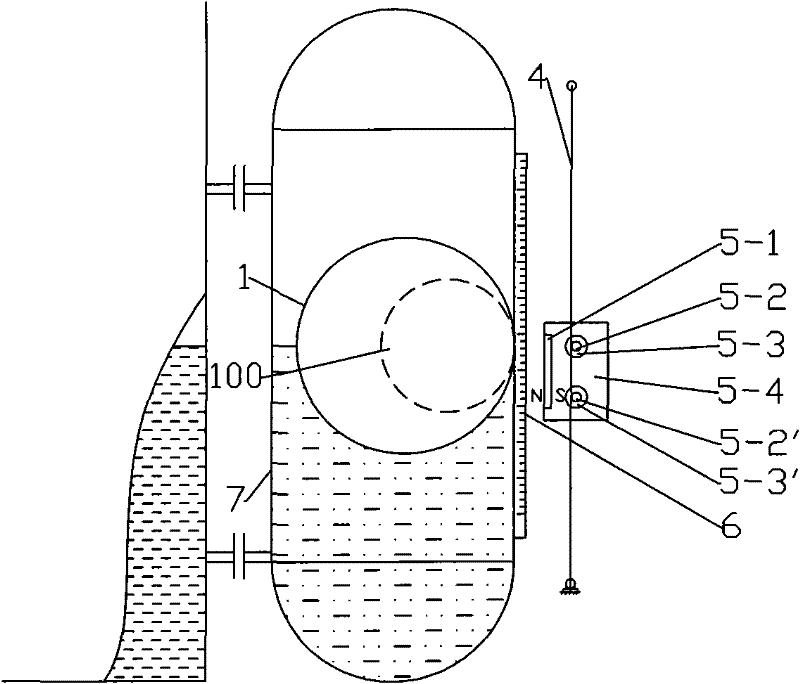
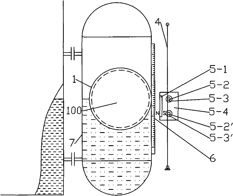
[0080] Such as figure 1 , 2, 3, 4 shows the float type level gauge includes a non-ferromagnetic material float chamber 7, a non-ferromagnetic material float 1, a scale outside the float 6, a magnetic coupling 5 and two guide rails 4; The two guide rails 4 are installed outside the float chamber 7 and are equidistant from the float chamber 7;

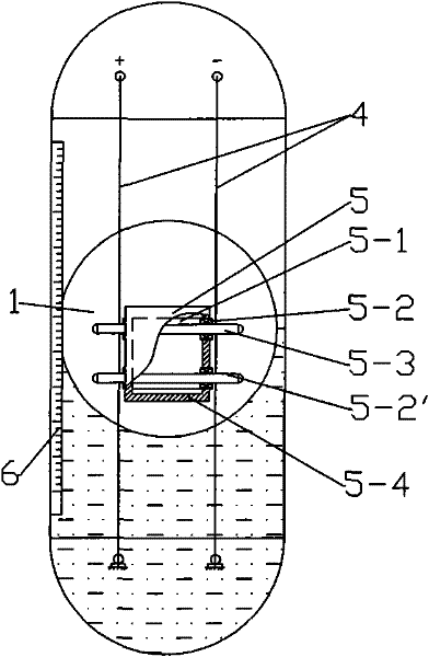
[0081] The float 1 is a hollow sphere with a ferromagnetic sphere 100 inside, such as figure 1 Shown; the sphere 100 can be hollow, and its outer diameter is the same as the inner diameter of the float 1, such as image 3 Shown

[0082] The magnetic coupling 5 is located between the two guide rails 4 and includes a magnetic steel 5-1 and a metal shaft 5-3; the magnetic steel 5-1 is located in the magnetic coupling 5 on the side close to the float 1, and its magnetic pole is positive To the float 1; the metal shaft 5-3 and the guide rail 4 are perpendicular to the two side walls of the magnetic coupling 5, both ends of which are exposed outsid...

Embodiment 2

[0089] Such as Figure 5 , The float-type level gauge shown in 6 includes a non-ferromagnetic material float chamber 7, a non-ferromagnetic material float 1, a magnetic coupling 5 and two guide rails 4; the two guide rails 4 are installed in the float chamber 7 outside and equidistant from the float chamber 7;

[0090] The float 1 is a hollow sphere, and more than one disc-shaped magnetic steel A10 with the same inner diameter as the float is installed in it;

[0091] The magnetic coupling 5 is located between the two guide rails 4 and includes a ring-shaped magnetic steel B5-5 and a metal shaft 53; the magnetic steel B5-5 is fixed at the center of the insulating box 5-4, and is connected to the The metal shaft 5-3 in the magnetic coupling 5 is coaxial, and the axes of the magnetic steel A10 and the magnetic steel B5-5 are parallel to each other and parallel to the ground. The magnetic poles of the two are located on their circular end faces and the two N and S poles In the opposi...

Embodiment 3

[0095] Such as Figure 7 , 8 and Picture 9 , 10 The difference between the float-type liquid level gauge shown in Embodiment 1 is that a pulley 3 is erected above the float chamber 1, and the two ends of the connecting rope or the connecting belt 2 are respectively connected to the magnetic coupling 5 and the counterweight 11, two The guide rail 4 is between the connecting ropes or connecting belts 2.

[0096] When the float 1 is immersed in half of the liquid to be measured, the weight of the counterweight 11 minus the gravity of the magnetic coupling 5 is equal to the weight of the float 1 minus the buoyancy that the float 1 experiences when it is immersed in half of the liquid to be measured. As a result, the counterweight 11 drives the magnetic coupling 5 to give the float 1 an upward lifting force and achieve a force balance.

[0097] When the liquid level rises and falls, the balance of this force is broken, and the magnetic coupling 5 and the counterweight 11 move up and do...


PUM


Abstract

The invention relates to a float type liquid level gauge for high temperature and high pressure or high pressure and low density medium, including a float chamber, a float, and a scale. The coupling is equipped with magnetic steel or disc-shaped magnetic steel, which forms a magnetic attraction with the magnetic material sphere in the non-ferromagnetic material float or the disc-shaped magnetic steel in the non-ferromagnetic material float, and is horizontally mounted on the magnetic coupling. The metal shafts on the two side walls are exposed outside the two side walls and are closely attached to the guide rails by the magnetic force, and move up and down along the guide rails driven by the magnetic force. The continuous remote transmission of signals is also realized by winding the resistance wire on the guide rail to measure the change of the loop resistance value. The invention solves the problem of liquid level measurement in high-temperature, high-pressure or high-pressure, low-density media, and has high measurement accuracy, simple structure, convenient use, low manufacturing and maintenance costs, and wide application.

Description

Technical field [0001] The invention relates to the field of liquid level measurement, in particular to a float type or magnetic float type liquid level gauge for high temperature, high pressure or high pressure and low density media. Background technique [0002] Liquid level gauge is an instrument with a wide range of applications. There are many types of liquid level measuring instruments available. Now for the high temperature and high pressure container, the medium is highly corrosive or the pressure is high but the medium density is low, the following analysis is made: [0003] In high pressure or high pressure low density applications, the float type liquid level meter is difficult to manufacture due to high pressure or high pressure and low medium density. For high temperature and high pressure applications, the manufacture of floats is even more difficult: When the strength decreases at high temperature, the wall thickness of the float needs to be increased accordingly. W...

Claims


Application Information

Patent Timeline
Patent Type & Authority Patents(China)
IPC IPC(8): G01F23/76G01F23/64G01F23/66G01F23/72
Inventor 王嘉贤陈长余王媛媛刘勇刘秋实金健迟云峰
Owner DALIAN CONSERVATION SCI & TECH CO LTD
Why Eureka
Try Eureka