
Infrared thermal imaging remote monitoring device for transmission tower

A technology of infrared thermal imaging and transmission tower

Inactive Publication Date: 2010-06-09
STATE GRID CORP OF CHINA +1
View PDF0 Cites 15 Cited by
  • Summary
  • Abstract
  • Description
  • Claims
  • Application Information

AI Technical Summary

Problems solved by technology

[0002] With the development of science and technology, the requirements for power supply reliability are getting higher and higher. Overhead high-voltage transmission lines are the most important part of the power system. Most of the high-voltage transmission lines are erected on high-altitude iron towers and operate under high-voltage and high-current conditions for a long time. , it is easy to cause faults, and the faults are mainly concentrated in the connection of the line, such as wiring tubes, wire clips, linear crimping tubes, bolts, jumper clips, parallel trench clips, adjustment boards, second-line connection boards, etc. Due to severe weather changes, the storm , heavy rain, snowstorm, and lightning will often aggravate the thermal effect of high-voltage transmission towers and lines, cause aging of metal materials, reduce mechanical properties, and generate partial discharges, resulting in burning, welding or fracture damage of connectors, directly affecting high-voltage high-voltage transmission lines safe operation of
[0003] At present, most of the inspections of transmission towers and lines use thermometers for inspection, which can only monitor the situation at that time, and cannot detect and alarm immediately; some use sensors to measure key parts. A tower needs dozens of sensors. Sensor protection, The installation costs are very high; although these methods can be monitored, they all have some disadvantages, and they cannot be measured online and intuitively around the clock

Method used


Image

  • Infrared thermal imaging remote monitoring device for transmission tower
  • Infrared thermal imaging remote monitoring device for transmission tower
  • Infrared thermal imaging remote monitoring device for transmission tower

Examples


Embodiment Construction

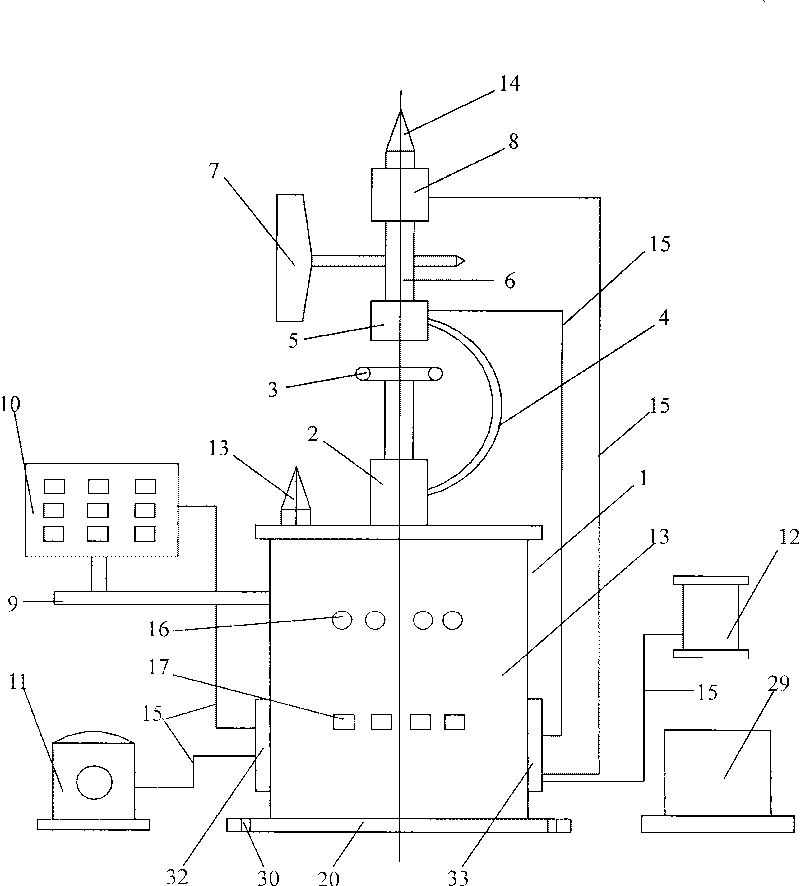
[0197] The present invention will be further described below in conjunction with accompanying drawing:

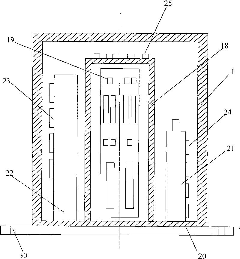
[0198] figure 1 Shown is the layout of the main chassis and its surroundings. The position and connection relationship of each part must be correct and the installation should be firm.

[0199] The main chassis is the main body of the device, made of stainless steel, good in strength, corrosion-resistant, and protective.

[0200] The wind speed scale, wind vane and sensor are set on the upper part of the main box to measure the wind direction and wind speed on the transmission tower and transmit them to the ground.

[0201] The solar panel transmits electric energy to the storage battery in the main chassis for storage of the circuit board operation and signal transmission.

[0202] Install an infrared thermal imager on the right side of the main box to monitor the temperature of the connecting board and the connecting terminal on the high-voltage transmission line tower,...


PUM


Abstract

The invention relates to an infrared thermal imaging remote monitoring device for a transmission tower. The monitoring device mainly comprises a main chassis, a circuit board, a screening box, a solar panel, a storage battery, a wind speed and wind direction sensor, a video camera, an infrared thermal imager, a 3G wireless communication transmitting antenna, a 3G wireless communication receiving antenna and a temperature and humidity sensor, wherein the wind speed, the wind direction, the environment, the temperature and the humidity and the thermal image situation of a connecting piece on the tower and dynamic images on the tower are synchronously transmitted to a ground industrial control computer; monitoring data is displayed and printed; the operating situation of the transmission tower is judged; and information-based, image-based and digital transmission monitoring on the transmission tower is realized. The device has the characteristics of advanced design, safety, stability, rapidness, accuracy, synchronization and reliability, and is a very ideal remote monitoring device for a high-voltage transmission tower. The device can also be used for monitoring wireless communication and television broadcasting towers.

Description

technical field [0001] The invention relates to an infrared thermal imaging remote monitoring device for a power transmission tower, and belongs to the technical field of monitoring equipment for a high-voltage power transmission tower. Background technique [0002] With the development of science and technology, the requirements for power supply reliability are getting higher and higher. Overhead high-voltage transmission lines are the most important part of the power system. Most of the high-voltage transmission lines are erected on high-altitude iron towers and operate under high-voltage and high-current conditions for a long time. , it is easy to cause faults, and the faults are mainly concentrated in the connection of the line, such as wiring tubes, wire clips, linear crimping tubes, bolts, jumper clips, parallel trench clips, adjustment boards, second-line connection boards, etc. Due to severe weather changes, the storm , heavy rain, snowstorm, and lightning will often...

Claims


Application Information

Patent Timeline
IPC IPC(8): G01P3/00G01P13/00G01K7/00G01N33/00H04N5/33G08C17/02
Inventor 杨北革吕玉祥张雅明薛辉占子飞代栓青
Owner STATE GRID CORP OF CHINA
Learn More