
Biological treatment device for exhaust gas

A technology of biological treatment and biological treatment pool, which is applied in the direction of air quality improvement, separation of dispersed particles, chemical instruments and methods, etc. It can solve problems such as difficulty in adapting to large-scale engineering applications, treatment effect not meeting requirements, troublesome collection and processing, etc. , to achieve the effect of good microbial film-hanging characteristics, convenient procurement and processing, and low price

Inactive Publication Date: 2010-06-16
广东省南方环保生物科技有限公司
View PDF0 Cites 5 Cited by
  • Summary
  • Abstract
  • Description
  • Claims
  • Application Information

AI Technical Summary

Problems solved by technology

Although the bark has good film-hanging properties and can provide nutrients for microorganisms, its porosity is small and resistance is large.
The use of bark as a filler is not only troublesome to collect and process, but also the source is unstable, making it difficult to meet the needs of large-scale engineering applications; and the bark itself can also be slowly degraded by microorganisms, so it needs to be replaced regularly, and the maintenance cost is high
PP multi-faceted ball has the advantages of large-scale production, large specific surface area, light weight, and long service life, but due to its hydrophobic nature, it is difficult for microorganisms to hang a film on it, resulting in small biomass, low processing load, and durability in biological treatment devices. The impact load is small, and the treatment effect often fails to meet the requirements; and nutrients and buffers need to be added to the circulating water regularly during operation, which is cumbersome to operate and high in operating costs

Method used


Image

  • Biological treatment device for exhaust gas
  • Biological treatment device for exhaust gas

Examples


Embodiment Construction

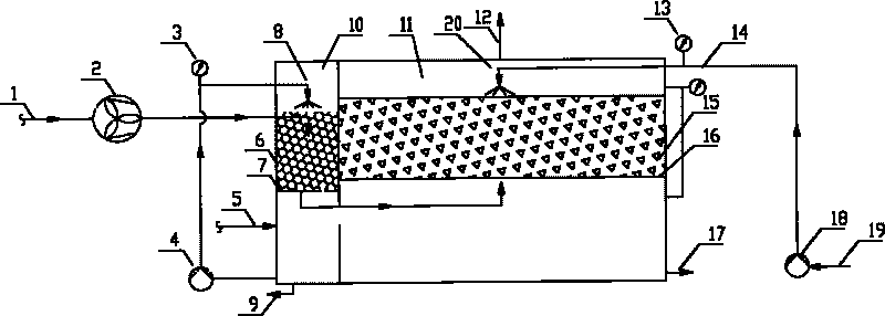
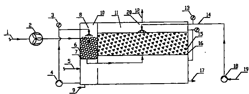
[0012] Such as figure 1 As shown, the exhaust gas is sent to the pre-wash tank 10 through the air inlet pipe 1 under the action of the air inlet fan 2, and the exhaust gas after passing through the spray packing layer 6 enters the biological treatment through the air outlet in the spray tank and the biological treatment tank. pool 11, and then discharge into the atmosphere by the exhaust pipe 12 at the upper end of the biological treatment pool after passing through the filler layer 15 of the biological treatment pool.

[0013] The spray water is continuously sprayed to the surface of the spray packing layer 6 through the spray nozzle 8 at high speed under the action of the spray water pump 4 (3-4 bar), forming a liquid film, and then enters the spray water pump 4 again through the spray water pipe. When the exhaust gas passes through the spray packing layer 6, it fully contacts with the liquid film formed on its surface, a part of the pollutants are absorbed into the spray wa...


PUM


Abstract

The invention discloses a biological treatment device for exhaust gas, which comprises two main parts, namely a prewashing tank and a biological treatment tank. The exhaust gas enters the biological treatment tank for purification after the exhaust gas is washed by spray water in the prewashing tank, wherein a filling in the biological treatment tank adopts a mixture of bioactivity ceramisites and oyster shells, and spray liquid of the biological treatment tank adopts precipitated outlet water of a secondary sedimentation tank of a sewage treatment plant. The biological treatment device for the exhaust gas has the characteristics: the adopted mixed filling has light weight, proper porosity, long service life, easy film formation and excellent hydrophilicity, is suitable for microorganisms to form films thereon, and has wide sources and low price; and the spray water adopts the precipitated outlet water of the secondary sedimentation tank, the requirement on the growth of the microorganisms can be met, the number of functional microorganisms in the biological treatment tank is effectively guaranteed, the operation procedure is simplified, the operating cost is effectively reduced, and the treatment efficiency is improved.

Description

technical field [0001] The invention relates to a biological treatment device for treating and purifying waste gas. Background technique [0002] At present, the known waste gas biological treatment device includes two main components of a pre-wash tank and a biological treatment tank. The pre-washing pool is mainly filled with pp multi-faceted ball packing, and the tap water is used for circular spray washing. The function of the pre-washing pool is to remove a part of the pollutants in the exhaust gas through good spray washing, and at the same time make the water content of the exhaust gas reach saturation. The filler in the biological treatment tank is mainly bark and PP multi-faced balls, and by adding nutrients to the filler or spray liquid, a microenvironment suitable for the growth and reproduction of specific functional microorganisms is created in the biological treatment tank. When the exhaust gas passes through the porous filler layer in the biological treatmen...

Claims


Application Information

Patent Timeline
Patent Type & Authority Applications(China)
IPC IPC(8): B01D53/84
CPCY02A50/20
Inventor 郑理慎方卫王薇陈志平张甜甜杨华
Owner 广东省南方环保生物科技有限公司
Learn More