System device with co-action of ultrasonic wave and far infrared ray on engine

A technology of far-infrared rays and system devices, which is applied in the direction of engine components, combustion engines, machines/engines, etc., can solve the problems that the products have not been widely used, and achieve the effects of stable and long-lasting emission efficiency, improved power, fuel saving and emission reduction power

Inactive Publication Date: 2010-06-16
王小亮
View PDF0 Cites 12 Cited by
  • Summary
  • Abstract
  • Description
  • Claims
  • Application Information

AI Technical Summary

Problems solved by technology

Therefore, these products have n

Method used


Image

  • System device with co-action of ultrasonic wave and far infrared ray on engine
  • System device with co-action of ultrasonic wave and far infrared ray on engine
  • System device with co-action of ultrasonic wave and far infrared ray on engine

Examples


Embodiment 1

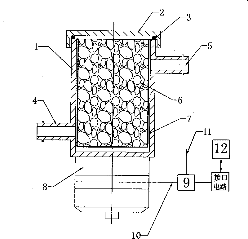
[0052] This example figure 1 Shown: figure 1 Described is the combined part of the fuel action unit, the ultrasonic generator and the single-chip microcomputer in the system device of the present invention. It is also the core part of the present invention. It includes housing 1, cover 2, sealing ring 3, oil inlet 4, oil outlet 5, far-infrared ceramics 6, filter element assembly 7, ultrasonic transducer 8 (the above constitutes a fuel action unit), ultrasonic Generator 9, signal line 10, power line 11, single-chip microcomputer 12.

[0053] The far-infrared ceramics 6 can be loaded into the housing 1 by opening the cover 2. In this embodiment, the far-infrared ceramics 6 are spherical in shape. The cover 2 and the housing 1 are screwed and fixed and sealed with a sealing ring 3 to prevent fuel oil and far-infrared ceramics 6 from leaking out. The filter element assembly 7 inside the housing 1 is used to prevent the far-infrared ray ceramics 6 from leaking out of the housin...

Embodiment 2

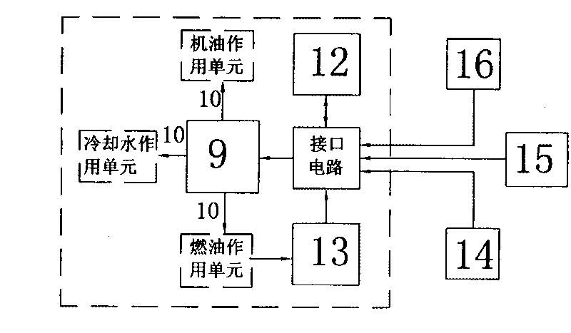
[0058] Such as figure 2 As shown, it is a schematic block diagram of the electronic control system containing the fuel oil action unit, the cooling water action unit, and the lubricating oil action unit with the single-chip microcomputer of the present invention.

[0059] Including fuel action unit, cooling water action unit, engine oil action unit, ultrasonic generator 9, single chip microcomputer 12, fuel temperature sensor 13, water temperature sensor 14, intake air temperature sensor 15, throttle opening sensor and / or speed sensor 16. The single-chip microcomputer 12 is respectively connected with the fuel temperature sensor 13, the water temperature sensor 14, the intake air temperature sensor 15, the throttle opening sensor and / or the speed sensor 16 and the ultrasonic generator 9 through an interface circuit. The fuel oil action unit of the above three action units is the fuel oil action unit described in Embodiment 1. On this basis, this embodiment further expands the...

Embodiment 3

[0073] In Embodiment 2, the fuel action unit and the engine oil action unit described in the present invention can also be extended in their functional application, that is, they can be used as a fuel filter and an oil filter respectively.

[0074] The following is only an example of extending the oil action unit to an oil filter:

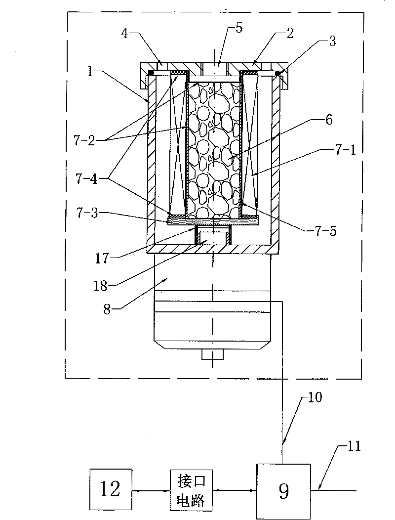
[0075] Such as image 3 Shown in the dotted line box is a view of the main structure of the oil action unit of this embodiment. Its structure is composed of shell 1, cover 2, sealing ring 3, oil inlet 4, oil outlet 5, far-infrared ceramics 6, paper filter element 7-1, metal filter 7-2, pressure plate 7-3, Gasket 7-4, support tube 7-5, ultrasonic transducer 8, elastic support 17, support seat 18.

[0076] The filter element assembly 7 described in the present invention is composed of a paper filter element 7-1 on the outer layer, an inner layer and an upper metal filter screen 7-2, a pressing plate 7-3, a gasket 7-4 and a support Tubes 7-5 are co...


PUM


Abstract

The invention discloses a system device with co-action of ultrasonic wave and far infrared ray on an engine, comprising a fuel action unit, a machine oil action unit, a cooling water action unit, an ultrasonic generator, a fuel temperature sensor and a singlechip. The action units are provided with far infrared ceramics and ultrasonic energy converters which are connected with the ultrasonic generator. The electric heaters of the three action units are electrically connected with the heating temperature controllers. The heating temperature controllers, the ultrasonic generator and one or more sensors are connected with a singlechip through an interface circuit. By using sound pressure generated in liquid medium of the ultrasonic wave, the system device raises temperatures of the fuel, machine oil and water medium so as to excite the far infrared ceramics in the medium and change macromolecule groups of the medium into micromolecule groups or single molecules under the action of far infrared ray, and the medium is activated adequately. The invention can remarkably enhance the dynamic property, the economical efficiency and the environmental-friendliness of the engine. The system device can be used as a fuel filter and a machine oil filter.

Description

technical field [0001] The invention relates to a system device in which ultrasonic waves and far infrared rays act together on an engine. It belongs to the field of engine technology. Background technique [0002] Because the fuel molecules are usually in an aggregated state before combustion, the large molecular clusters in the aggregated state prevent the fuel from being sprayed from the nozzle to achieve a complete atomization state, so that the fuel cannot be fully combusted in the engine. Then just can not further improve the fuel economy of engine, power and the environmental protection property that reduces tail gas emission. [0003] And in present existing fuel-saving technology, the form of its fuel-saving device is generally the method for simply connecting in series in the engine oil inlet pipe or adding far-infrared functional material outside the oil inlet pipe. Wherein the method of installing far-infrared functional material outside the oil pipe, because t...

Claims


Application Information

Patent Timeline
IPC IPC(8): F02M27/00F02M27/06F02M27/08
CPCY02T10/126Y02T10/12
Inventor 王小亮
Owner 王小亮
Why Eureka
Try Eureka