Plasma processing apparatus and constituent part thereof

A plasma and processing device technology, which is applied in the field of plasma processing devices and their constituent parts, and can solve problems such as reduction of removal amount and the like

Active Publication Date: 2010-06-16
TOKYO ELECTRON LTD
View PDF1 Cites 5 Cited by
  • Summary
  • Abstract
  • Description
  • Claims
  • Application Information

AI Technical Summary

Problems solved by technology

As a result, in the corner portion 73, the number of ions 75 implanted per unit area is extremely small compared with other portions, thereby reducing the removal amount of deposits caused by the sputtering of the ions 75. Situation of accumulation of sediment 76 at the corner 73 and its vicinity

Method used


Image

  • Plasma processing apparatus and constituent part thereof
  • Plasma processing apparatus and constituent part thereof
  • Plasma processing apparatus and constituent part thereof

Examples


Embodiment Construction

[0037] Hereinafter, embodiments of the present invention will be described with reference to the drawings.

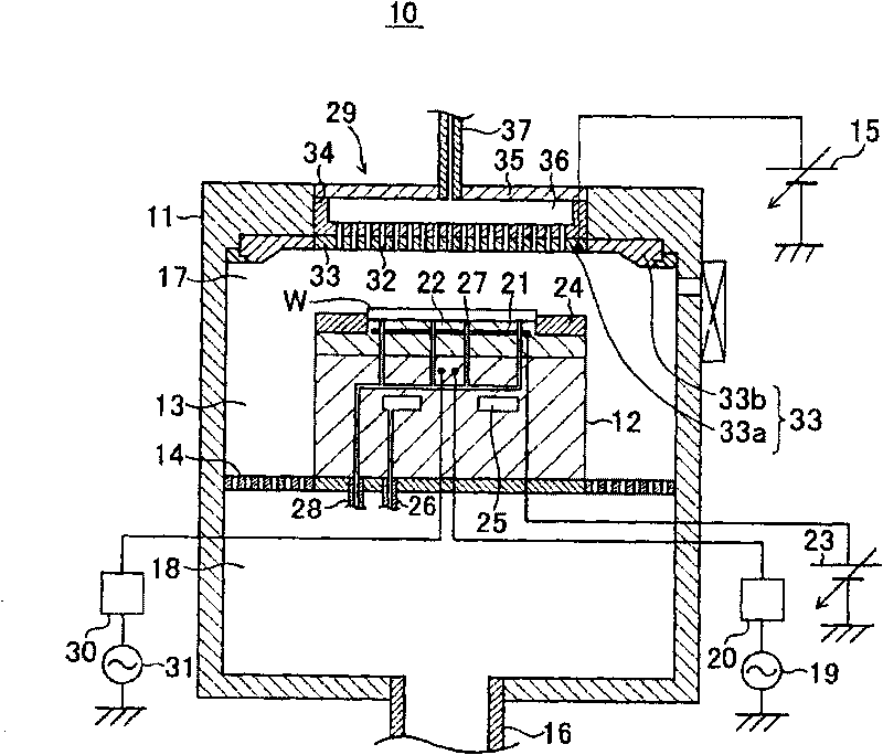
[0038] figure 1 It is a cross-sectional view schematically showing the structure of a plasma processing apparatus including the constituent members according to this embodiment. The plasma processing apparatus is configured to perform dry etching processing on a wafer.

[0039] in figure 1 Here, the plasma processing apparatus 10 has a chamber 11 that houses a wafer W having a diameter of, for example, 300 mm, and a cylindrical susceptor 12 on which a wafer W for semiconductor equipment is placed is arranged in the chamber 11. In addition, in the plasma processing apparatus 10, through the inner side wall of the chamber 11 and the side surface of the susceptor 12, a lateral exhaust passage 13 that functions as a passage for discharging the gas above the susceptor 12 to the outside of the chamber 11 is formed . An exhaust plate 14 is arranged in the middle of the side exh...


PUM


Abstract

In an outer electrode 33b of an upper electrode (33) which is provided in a plasma processing apparatus 10 that uses plasma for forming dry etching process for wafers W, an angle [theta]1 of a corner 33e formed by an inner peripheral portion 33c and an inclined surface 33d is set to be 140 degrees. An angle [theta]2 of a corner 41c formed by a bottom surface 41a and an inclined surface 41b of a groove 41 is set to be 125 degrees. Also, an angle [theta]3 of a corner 41e formed by the bottom surface 41a and an inclined surface 41d of the groove 41 is set to be 125 degrees. The width L of the bottom surface 41a of the groove 41 is set to be twice or more the length of the sheaths.

Description

Technical field [0001] The present invention relates to a plasma processing device and its constituent parts, and more particularly to a constituent part of a plasma processing device exposed to plasma. Background technique [0002] The plasma processing apparatus includes a housing chamber that houses a wafer as a substrate, generates plasma from a processing gas introduced into the housing chamber, and performs desired plasma processing on the wafer by the plasma. When the plasma treatment is a dry etching treatment, a reaction product is generated due to the plasma and the substance to be etched, and the reaction product is deposited as a deposit on the surface or the like of the component constituting the storage chamber. [0003] On the other hand, a sheath 71 is generated along the surface 70 of each component exposed to the plasma in the containing chamber, and ions 72 in the plasma are injected into the surface of each component through the sheath 71 ( Figure 7 (A)). The i...

Claims


Application Information

Patent Timeline
Patent Type & Authority Applications(China)
IPC IPC(8): H01J37/04H01J37/32
CPCH01J37/32477H01J37/32541
Inventor 村上贵宏若木俊克
Owner TOKYO ELECTRON LTD
Why Eureka
Try Eureka