Method for removing various gaseous pollutants from smoke gas

A pollutant and flue gas technology, applied in the field of flue gas purification, can solve the problems of low absorption capacity, large MEA loss, high cost, etc., and achieve the effect of low removal cost, high mercury removal performance, and easy realization

Inactive Publication Date: 2010-06-23
NORTH CHINA ELECTRIC POWER UNIV (BAODING)
View PDF2 Cites 57 Cited by
  • Summary
  • Abstract
  • Description
  • Claims
  • Application Information

AI Technical Summary

Problems solved by technology

The technology adopts MEA decarbonization, which has high cost, large loss of MEA, CO 2 Problems such as low absorption capacity a

Method used


Image

  • Method for removing various gaseous pollutants from smoke gas
  • Method for removing various gaseous pollutants from smoke gas
  • Method for removing various gaseous pollutants from smoke gas

Examples


Embodiment 1

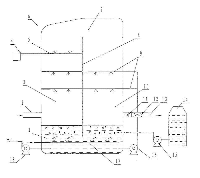
[0018] Embodiment 1: see figure 1 The bottom of the absorption tower 6 is provided with an absorption slurry pool 1; the middle part is provided with a spray pipe 9, and the spray pipe is connected to the absorption liquid pool by an absorption liquid circulation pump 16 and pipelines, and the pH value of the absorption liquid in the absorption slurry pool is maintained at 5 to 7. The absorption liquid is ammonia water; the upper part of the absorption tower is provided with an oxidant pipe 5, the oxidant is ozone, and the ozone is added to the oxidation zone 7 in the gas phase, because most of the SO 2 It is removed in the desulfurization section 3, reducing the SO 2 The amount of ozone consumed by oxidation, thereby reducing the consumption of ozone by the system, the oxidant pipe is connected to the ozone generator 4, and the added ozone and the NO in the flue gas X Molar ratio (O 3 / NO) is controlled within the range of 0.5 to 2.0, in this embodiment NO X molar ratio O ...

Embodiment 2

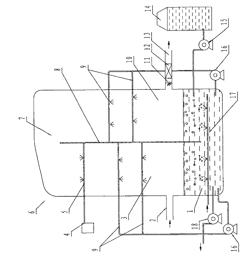
[0045] Embodiment 2: see figure 2 , the 90-120°C flue gas enters the desulfurization section 3 from the absorption tower inlet 2, and the SO 2 In the removal of HCl and HCl, the flue gas in the desulfurization working section flows upwards, and after contacting and reacting with the absorption liquid (ammonia water) sprayed from the spray pipe 9, the temperature drops to 50-100°C, and the SO 2 and HCl removal; the flue gas continues upward into the oxidation zone, where NO in the flue gas is oxidized to a higher oxidation state of NO by the ozone ejected from the oxidizer pipe X , while elemental mercury is oxidized to divalent mercury, NO in this example X molar ratio O 3 / NO is 1.0; the flue gas continues to descend into the denitrification and decarbonization working section 10, and the highly oxidized NO in the flue gas in this working section X , divalent mercury and CO 2 React with the spray pipe 9 to spray the absorption liquid to complete the NO X , mercury vapor...

Embodiment 3

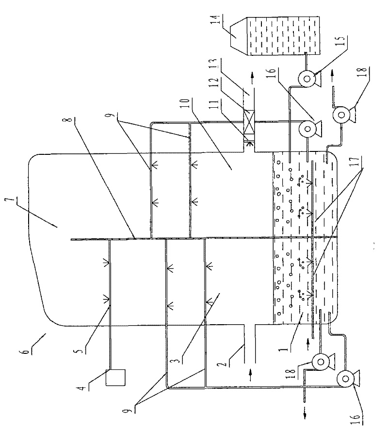
[0046] Embodiment 3, see image 3 , the 90-120°C flue gas enters the desulfurization section 3 from the absorption tower inlet 2, and the SO 2 In the removal of HCl, the flue gas in the desulfurization working section flows upwards, and after contacting and reacting with the absorption liquid sprayed by the spray pipe 9, the temperature drops to 50-100°C, and the SO 2 and the removal of hydrogen chloride; the flue gas continues upward into the oxidation zone 7, where NO in the flue gas is oxidized by ozone to a higher oxidation state of NO X , while elemental mercury is oxidized to divalent mercury, NO in this example X molar ratio O 3 / NO is 2.0; the flue gas continues to descend into the denitrification and decarbonization working section 10, and the highly oxidized NO in the flue gas in this working section X , divalent mercury and CO 2 React with the spray pipe 9 to spray the absorption liquid to complete the NO X , mercury vapor and CO 2 remove. The clean flue gas ...


PUM


Abstract

The invention provides a method for removing various gaseous pollutants from smoke gas, which is used for solving the problem of limitation of the control and government technology on various pollutants in the smoke gas. The invention utilizes an absorption tower for fully removing SO2, NOX, mercurial vapor and CO2 in the smoke gas, the lower part of the absorption tower is provided an absorptionpulp tank, the middle of the absorption tower is provided with a spraying pipe, the upper part of the absorption tower is provided with an oxidizing agent pipe, the absorption tower is provided with partition boards in the vertical direction, both sides of the partition boards are respectively a desulfurization work section and a denitration and decarburization work section, the upper part of theabsorption tower is a communication oxidization region, the smoke gas enters the desulfurization work section from an inlet of the absorption tower to complete the removal of SO2 and HCL, the smoke gas continuously goes upwards to enter the oxidization region, and NOX is oxidized into water-soluble high oxide in the oxidization region and then enters the denitration and decarburization work section to complete the removal of the NOX, the mercurial vapor and the CO2. The invention breaks through the technical bottlenecks of complicated equipment and high running cost for simultaneously removing various gaseous pollutants from the smoke gas in the prior art. The process method and the device of the invention have the unique novelty.

Description

technical field [0001] The invention relates to a method for purifying flue gas, in particular to a method for removing various gaseous pollutants in the flue gas of power station boilers and industrial boilers, and belongs to the technical field of flue gas purification. Background technique [0002] It is well known that sulfur dioxide (SO 2 ) and nitrogen oxides (NOx), forming acid rain and other secondary pollutants, which have seriously affected human production and life. Therefore, SO 2 The control and purification of NOx is imminent, which is related to the development of the national economy and the survival of human beings. [0003] Flue gas desulfurization (FGD) is the only large-scale commercial application of desulfurization method in the world at present, it is the control of acid rain and SO 2 Pollution is the most effective and main technical means. The mainstream technology is the wet limestone gypsum washing method. Its technology is relatively mature, i...

Claims


Application Information

Patent Timeline
IPC IPC(8): B01D53/78B01D53/60B01D53/62B01D53/64B01D53/66B01D53/54
CPCY02A50/20
Inventor 马双忱赵毅苏敏孙云雪
Owner NORTH CHINA ELECTRIC POWER UNIV (BAODING)
Why Eureka
Try Eureka