
Method for preparing natural gas by dry quenching co-production coal

A coal-to-natural gas and coke CDQ technology, which is applied in coke cooling, combustible gas production, coke oven, etc., can solve the problems of reducing the unit calorific value of pyrolysis gas, fuel consumption, air pollution, etc., and achieve simplified operation process and equipment maintenance, investment reduction, water saving effect

Inactive Publication Date: 2010-06-23
山西中元煤洁净技术有限公司
View PDF4 Cites 20 Cited by
  • Summary
  • Abstract
  • Description
  • Claims
  • Application Information

AI Technical Summary

Problems solved by technology

[0008] In the above-mentioned coal pyrolysis methods, combustion mechanisms are designed, which consume a large amount of fuel and increase energy consumption; at the same time, a large amount of dust and waste gases such as carbon dioxide, sulfur dioxide and nitrogen oxides are produced, causing serious air pollution; at the same time The combustion exhaust gas dilutes the pyrolysis gas and reduces the unit calorific value of the pyrolysis gas

Method used


Image

  • Method for preparing natural gas by dry quenching co-production coal

Examples


Embodiment 1

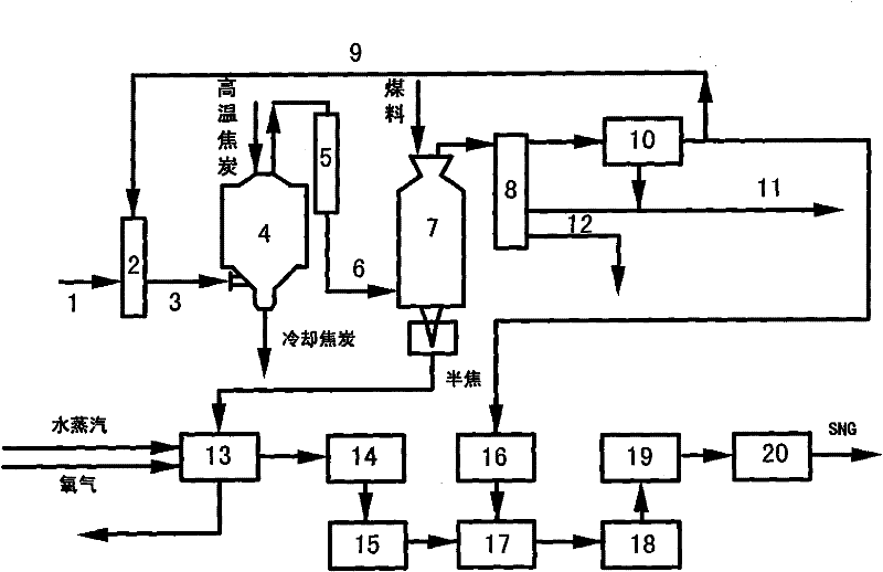
[0031] Such as figure 1 , to implement the method of CDQ co-production of coal-to-natural gas, firstly, the reducing gas is passed into the gas mixer 2 through the reducing gas pipeline 1, and the circulating heat-carrying gas is passed into the gas mixer 2 through the circulating heat-carrying gas pipeline 9 . The reducing gas and the circulating heat-carrying gas are mixed in the gas mixer 2 to form a cold heat-carrying gas, and the cold heat-carrying gas is passed through the heat-carrying gas pipeline 3 from the bottom of the coke quenching tower 4 . The main component of the reducing gas is H 2 , CO and CH 4 , the sum of the volume fractions of the three should be greater than 70%; the circulating heat-carrying gas is a part of the clean gas after the crude gas output from the top of the coal pyrolyzer 7 has been cooled and purified. The high-temperature coke at 900°C-1050°C is loaded into the quenching tower 4 from the top of the quenching tower 4, and the cold heat-c...

Embodiment 2

[0033] Such as figure 1 , to implement the method of CDQ co-production of coal-to-natural gas, firstly, the reducing gas is passed into the gas mixer 2 through the reducing gas pipeline 1, and the circulating heat-carrying gas is passed into the gas mixer 2 through the circulating heat-carrying gas pipeline 9 . The reducing gas and the circulating heat-carrying gas are mixed in the gas mixer 2 to form a cold heat-carrying gas, and the cold heat-carrying gas is passed through the heat-carrying gas pipeline 3 from the bottom of the coke quenching tower 4 . The main component of the reducing gas is H 2 , CO and CH 4 , the ratio of the three can be zero in theory, but in practice, its H 2 , CO and CH 4 One of the three cannot be zero, because in general, coke oven gas is used, not pure gas, no matter the proportion of the three, as long as the sum of the three volume fractions should be greater than 70%; The hot gas is a part of the clean gas after the crude gas output from t...


PUM


Abstract

The invention provides a method for preparing natural gas by dry quenching co-production coal. In the method, reducing gas is taken as heat-carrying gas, refrigerant and a pyrolytic process thereof are adopted to recover a great quantity of sensible heat of high-temperature coke so as to couple the dry-method coke quenching process and the coal pyrolytic process of high-temperature metallurgical coke, thus cancelling a gas and air supply system, a combustion control system and a waste gas discharging system in the original pyrolytic process, avoiding pyrolytic combustion process, saving a great quantity of energy, and realizing smoke-free, NOX-free, SOX-free and CO2-free discharging. Meanwhile, gasification gas produced by pyrolytic gas and semi-coke gasification is used for producing andsynthetizing natural gas in a methanation manner so as to realize clean conversion of coal. In addition, the method cancels N2 preparation equipment and waste heat boiler systems in dry quenching, thus simplifying the operation and maintenance process and greatly lowering investment and operation cost.

Description

technical field [0001] The invention relates to a coke cooling method in which cold coal and its pyrolysis process are used to absorb heat energy of high-temperature coke in the coking process, and a method for producing gasified coal gas by using hot semi-coke as a raw material, and using a mixture of gasification coal gas and pyrolysis coal gas to produce The natural gas method, specifically, is a method for dry quenching and co-production of coal to natural gas. Background technique [0002] The "CDQ method and device" whose publication number is CN1694943A puts high-temperature coke from the top of the pre-chamber, blows cooling gas (mainly nitrogen) from the bottom of the pre-chamber, and cools the gas and high-temperature coke in countercurrent contact in the cooling chamber. exchange. The high-temperature gas after heat exchange is sent to the waste heat boiler after dust removal, and steam is generated through the waste heat boiler system to recover the heat energy ...

Claims


Application Information

Patent Timeline
Patent Type & Authority Applications(China)
IPC IPC(8): C10B49/02C10B39/02C10L3/08C10J3/66
CPCY02P20/129
Inventor 张永发杨力梁言王磊
Owner 山西中元煤洁净技术有限公司
Learn More