
Rotor-free sensor motor driver and vehicle having same

A sensor and drive technology, applied in the direction of electric vehicles, electronic commutation motor control, motors, etc., can solve the problems of heavy motor load, loud motor noise, strong vehicle vibration, etc., to improve electrical efficiency, increase mileage, and start smooth effect

Inactive Publication Date: 2010-06-23
何伟斌
View PDF0 Cites 9 Cited by
  • Summary
  • Abstract
  • Description
  • Claims
  • Application Information

AI Technical Summary

Problems solved by technology

[0003] The existing rotorless sensor motor driver also adopts the back electromotive force detection of the motor phase line to determine the commutation time, but when the motor is started, it needs to do a stepping method to let the motor rotate first to generate a back electromotive force. The stepping method Whether it can start successfully depends on the load of the motor and the driving current in the stepping mode, and the vibration of the motor is particularly large. Due to the vibration of the motor, the back electromotive force generated is unstable and it is difficult to start successfully.
When using this driver on an electric vehicle, due to the heavy load and large fluctuations of the motor when starting, the vehicle will vibrate strongly when starting, and the riders have different styles, so it is difficult to control the smooth start of the vehicle
[0004] The existing motor driver without rotor sensor generally adopts the working method of two tubes conducting six beats, and the motor emits a large noise when commutating phases

Method used


Image

  • Rotor-free sensor motor driver and vehicle having same
  • Rotor-free sensor motor driver and vehicle having same

Examples


Embodiment Construction

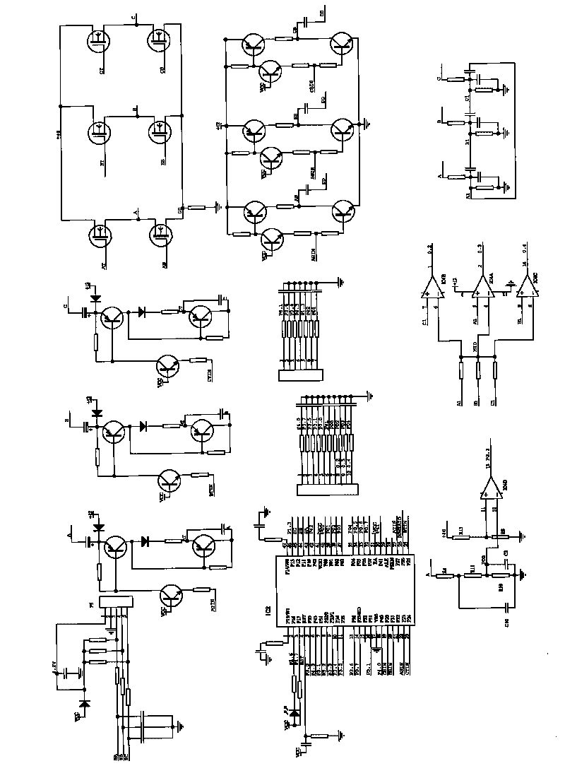
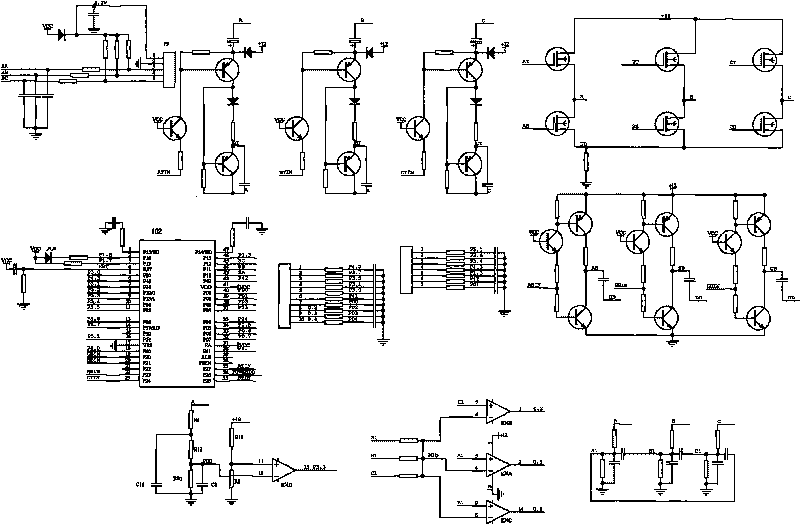
[0012] A driver for a motor without a rotor sensor, comprising a control circuit, a power drive circuit, characterized in that it has a three-phase phase-shifting comparison circuit, a counter electromotive force zero-crossing detection circuit, and the counter electromotive force zero-crossing detection circuit includes a phase line voltage divider circuit, The output of the three-phase shifting comparison circuit is electrically connected to the single-chip electromechanical device in the control circuit, and the counter electromotive force zero-crossing circuit is electrically connected to the single-chip electromechanical device; the counter electromotive force zero-crossing circuit is electrically connected to the single-chip electromechanical device through a comparator , one input of the comparator is connected to the phase line voltage divider circuit, and the other input end of the comparator is connected to the power supply voltage divider circuit; the phase line volta...


PUM


Abstract

The invention discloses a driver of a rotor-free sensor motor, which comprises a control circuit and a power driving circuit, and is characterized by having a three-phase phase-shift comparison circuit and a counter electromotive force zero crossing point detection circuit, wherein the counter electromotive force zero crossing point detection circuit comprises a phase-line voltage-division circuit, the output of the three-phase phase-shift comparison circuit is electrically connected with a single chip in the control circuit, and the counter electromotive force zero crossing point detection circuit is electrically connected with the single chip; when the motor runs at different rotation speeds and has different loads, the driver can change the phase correctly and is stable to start, thereby improving the electric efficiency of the motor; and the driver is applied to an electric vehicle, the electric vehicle is free from shaking after being started, and the driving miles of the vehicle can be improved.

Description

technical field [0001] The invention relates to the field of a brushless DC motor without a rotor sensor, and also relates to a vehicle equipped with the motor. Background technique [0002] In the existing rotorless sensor motor driver, the phase line of the motor is generally filtered, and the three-phase pulse generated by phase shifting is fed back to the microcontroller as a commutation signal. The phase shift angle of the commutation signal is related to the speed, motor load, and motor power. , so that the commutation angle of the motor is shifted. Once the shift of the commutation angle occurs, the output torque of the leading or lagging motor will decrease, and the input current of the power supply will increase, so the electrical efficiency will decrease. When this drive is used on an electric vehicle, the acceleration force is obviously insufficient, the maximum speed per hour is obviously reduced, and the continuation mileage is obviously shortened. [0003] The...

Claims


Application Information

Patent Timeline
IPC IPC(8): H02P6/18H02P6/20B60L11/18H02P6/182
CPCY02T10/642Y02T10/7005Y02T10/64
Inventor 何伟斌
Owner 何伟斌
Learn More