Test device for simulating and testing thermal fatigue failure of high-temperature part in real time

A technology for high-temperature components and test devices, applied to measuring devices, instruments, scientific instruments, etc., to achieve the effects of wide temperature range, fast heating and cooling rates, and simple operation

Active Publication Date: 2010-06-30
XIANGTAN UNIV
View PDF2 Cites 69 Cited by
  • Summary
  • Abstract
  • Description
  • Claims
  • Application Information

AI Technical Summary

Problems solved by technology

[0005] The purpose of the present invention is to solve the thorny problems existing in the existing real-time detection of thermal fatigue failure of high-temperature components, to provide a test device for simulating and real-time testing of thermal fatigue failure of

Method used


Image

  • Test device for simulating and testing thermal fatigue failure of high-temperature part in real time
  • Test device for simulating and testing thermal fatigue failure of high-temperature part in real time
  • Test device for simulating and testing thermal fatigue failure of high-temperature part in real time

Examples


Example Embodiment

[0029] The present invention provides a test device for simulating and real-time testing of the thermal fatigue failure of high-temperature components. The present invention will be further described below through the description of the drawings and the specific embodiments.

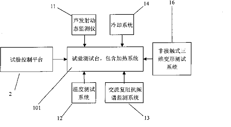
[0030] Such as figure 1 As shown, the structure of the test device includes: a test test bench, a high-temperature gas bidirectional heating system connected to the test test bench, a temperature test collection system 12, a cooling system 14, a non-contact three-dimensional deformation test system 16, and a non-destructive acoustic emission Detection system 11, AC complex impedance spectrum monitoring system 13, Test control platform 2.

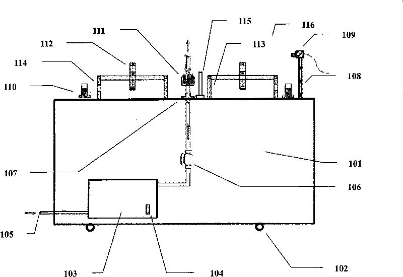
[0031] Such as figure 2 As shown, the structure of the test test bench is as follows: a clamp 111 for clamping the sample 5 and a clamp fixing device 107 are installed in the middle of the test test platform 101, and the upper and lower positions of the clamp 111 are adjust...


PUM

PropertyMeasurementUnit
Sensitivityaaaaaaaaaa

Abstract

The invention belongs to the field of high-temperature part detecting equipment, in particular to a test device for simulating and testing the thermal fatigue failure of a high-temperature part in real time. The device mainly comprises a high-temperature gas two-way heating system, a real-time temperature testing and collecting system, a cooling system, an ARAMIS non-contact three-dimensional deformation test system, a PCI-2 AE non-destructive detection system, a 1260+1296-type material electric property AC impedance spectroscopy test system, a test control platform and the like. The device can simulate the thermal fatigue work environment of alternating temperature cycle in a high-performance aircraft engine, and synchronously realize the real-time testing and the analysis to the sample temperature, temperature gradient, surface morphology image evolution, three-dimensional deformation field, three-dimensional displacement field, interfacial oxide layer and thickening law, thermal fatigue crack initiation and propagation, cooling gas flow and other data. The device can provide an important experimental platform for effectively evaluating the fatigue failure process and the failure mechanism of the high-temperature part in the high-temperature thermal cycle environment.

Description

technical field [0001] The invention belongs to the field of high-temperature component detection equipment, and specifically relates to a test device for simulating and real-time testing of thermal fatigue failure of high-temperature components, in particular to a test device for simulating high-temperature high-temperature alloys of aeroengines and thermal barrier coatings Thermal fatigue working environment of components, and a test device for real-time testing of multiple thermal fatigue failure parameters. Background technique [0002] In recent years, with the development of aero-engines in the direction of high bypass ratio, high thrust-to-weight ratio, and high turbine inlet temperature, the operating temperature of high-temperature components of the engine is getting higher and higher, especially the gas temperature and gas pressure in the combustion chamber are constantly increasing, such as gas pressure Compared with the first-generation machine, it has been incre...

Claims


Application Information

Patent Timeline
IPC IPC(8): G01N17/00
Inventor 周益春毛卫国吴多锦杨丽
Owner XIANGTAN UNIV
Why Eureka
Try Eureka