Power module test system and test method thereof

A power module and test system technology, applied in the direction of single semiconductor device testing, etc., can solve problems such as poor flexibility, high test cost, and incomplete assessment of device performance, and achieve the effects of improving comprehensiveness, reducing test cost, and reducing capacity

Inactive Publication Date: 2010-06-30
ZHUZHOU CSR TIMES ELECTRIC CO LTD
View PDF0 Cites 25 Cited by
  • Summary
  • Abstract
  • Description
  • Claims
  • Application Information

AI Technical Summary

Problems solved by technology

[0004] The purpose of the present invention is to provide a power module test system with high test coverage, low test cost and high flexibility in view of the shortcoming

Method used


Image

  • Power module test system and test method thereof
  • Power module test system and test method thereof
  • Power module test system and test method thereof

Examples


Example Embodiment

[0031] The drawings show specific embodiments of the present invention, and the present invention will be further described below through the drawings and embodiments.

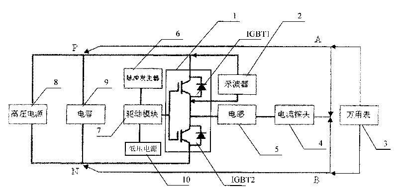
[0032] As a preferred implementation of the power module test system, such as figure 1 The power module test system shown includes:

[0033] Oscilloscope 2, multimeter 3, current probe 4, inductor 5, pulse generator 6, drive module 7, high-voltage power supply 8, low-voltage power supply 10, pulse generator 6 to generate pulses with variable widths, which are amplified by drive module 7 to control power switching devices The on-off of the IGBT is used to control the output voltage and current of the IGBT power module 1 to achieve the purpose of evaluating the performance of the power device. The low-voltage power supply 10 provides 5V power to the pulse generator 6 and 5V, ±15V power to the drive module 7. The high-voltage power supply 8 is used to charge the capacitor 9 of the IGBT power module 1 under test. The...


PUM


Abstract

The invention relates to a power module test system and a test method thereof, which comprises an oscilloscope, a multimeter, a current probe, an inductor, a pulse generator, a drive module, a high voltage power source and a low voltage power source, wherein the low voltage power source provides power source for the pulse generator and the drive module, the high voltage power source charges a capacitor of an IGBT power module to be tested, the oscilloscope acquires the voltage and current waveforms of the IGBT power module, and the inductor is connected between the C pole and the E pole of the IGBT power module via the current probe. Electric quantity in the charged capacitor is utilized for power module testing, and the characteristic that inductive load has barrier effect on varied current is utilized to test the follow current capacity of a diode in the IGBT power module. The invention not only can reduce the capacity of the required power supply source and save cost, but also increases test coverage rate.

Description

technical field [0001] The invention relates to a power module testing system and its testing method applied in the field of power semiconductors, especially a chopper testing system and its testing method applied to the performance parameter testing of IGBT power modules. The system and method can also be used for power Testing of performance parameters of other similar power modules in the semiconductor field. Background technique [0002] At present, there are many types of converter product modules and various test methods. The traditional test method uses the continuous chopping test method to test the power device. This method uses a resistive load. During the chopping test, the power supply needs to continuously charge the supporting capacitor. The control unit continues to provide continuous pulse signals to the driving circuit of the switching device under test to drive the switching device to turn on and off, thereby detecting a series of key performance indicators...

Claims


Application Information

Patent Timeline
IPC IPC(8): G01R31/26
Inventor 武松剑易卫华周利军陈长春谢明明李涛刘丹陈义韬
Owner ZHUZHOU CSR TIMES ELECTRIC CO LTD
Why Eureka
Try Eureka