

Numerical control scanning waveform generator
A technology of scanning waveforms and generators, which is applied in semiconductor/solid-state device manufacturing, discharge tubes, electrical components, etc., can solve problems such as complex injection processes, achieve isolation potential interference, save control costs, and meet horizontal scanning accuracy requirements Effect
- Summary
- Abstract
- Description
- Claims
- Application Information
AI Technical Summary
Problems solved by technology
Method used
Image

Examples
Embodiment Construction
[0027] The present invention will be further introduced below in conjunction with the accompanying drawings and specific embodiments, but it is not intended as a limitation to the novelty of the present invention.
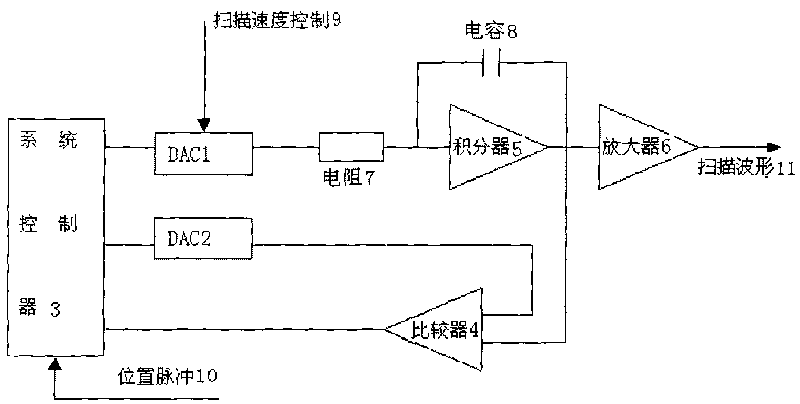
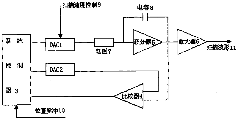
[0028] As shown in Fig. 1, the numerical control scanning waveform generator realizes the general schematic diagram of scanning waveform output, the system controller 3 controls the ion beam scanning, and the scanning waveform can be a piecewise linear curve defined by the slope and the end point of each segment. The data defining the waveform is stored in the waveform memory in the system controller 3, and the system controller 3 loads the data of the slope and the position end signal into two D / A converters of DAC1 and DAC2 respectively. The output of DAC1 drives the integrator 5, the output of the integrator 5 and the output of DAC2 are supplied to the input terminal of the comparator 4, when the integrator 5 reaches the end point of the specified position, the c...
PUM
 Abstract
Description
Claims
Application Information