Hydrogenation method for residual oil

A technology of residual oil and hydrogenation reaction, which is applied in the field of hydrogenation of residual oil, can solve the problems of long operating cycle, low catalyst utilization rate, and short operating cycle, etc., to extend the operating cycle, increase operating efficiency, and improve Economical effect

Active Publication Date: 2010-07-07
CHINA PETROLEUM & CHEM CORP +1
View PDF3 Cites 52 Cited by
  • Summary
  • Abstract
  • Description
  • Claims
  • Application Information

AI Technical Summary

Problems solved by technology

[0008] The object of the present invention is to overcome the shortcoming of the operation cycle of the device existing in the above-mentioned prior art, and the utilization rate o

Method used


Image

  • Hydrogenation method for residual oil
  • Hydrogenation method for residual oil
  • Hydrogenation method for residual oil

Examples


Embodiment 1

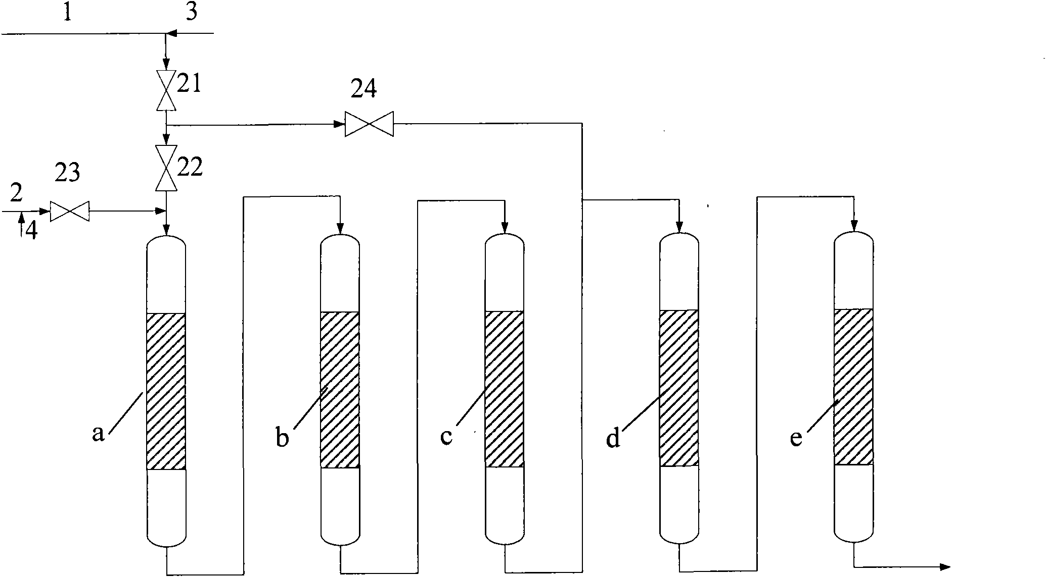
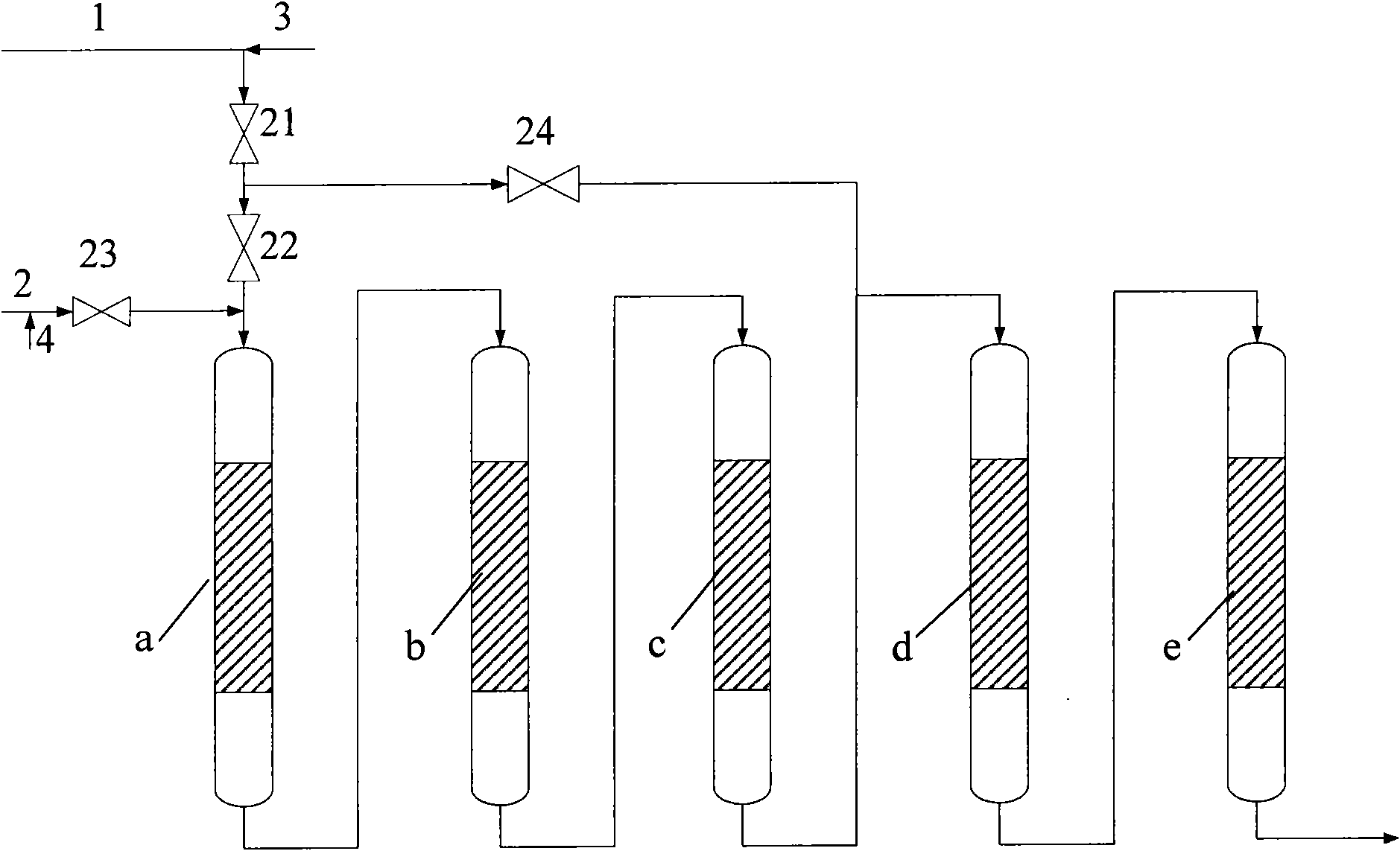
[0042] like figure 1 As shown, the device of the present invention is a self-designed fixed-bed hydroprocessing test device, which adopts five reactors with a volume of 5 liters in series and a top-down process flow for raw oil. The first hydrogenation reaction zone includes Three reactors are a reactor, b reactor and c reactor. The second hydrogenation reaction zone includes two reactors, namely d reactor and e reactor. A feeding line connected to the residue raw material pipeline 1 is arranged at the feed port. The designed maximum pressure drop of each reactor is 1.0MPa.

[0043] The catalysts used are a full series of residual oil hydrotreating catalysts developed by the Research Institute of Petrochemical Sciences, among which, RG, RDM and RMS series heavy and residual oil hydrogenation protection catalysts, hydrodemetallization catalysts and hydrodesulfurization catalysts are composed of catalysts Produced by Changling Branch.

[0044] The loading situation of catalys...

Embodiment 2

[0057] The same fixed-bed hydrotreating test device as in Example 1 was used.

[0058] The catalysts and loading conditions adopted in the first four reactors are the same as in Example 1, and the hydrodesulfurization catalyst RMS-1 and the hydrodenitrogenation catalyst RSN are filled from top to bottom in the e reactor of the second hydrogenation reaction zone -1, the filling ratio is 85:15.

[0059] The process of hydrogenation reaction of residual oil is as follows: when the reaction pressure is 15.0MPa, the reaction temperature is 385°C, the hydrogen-oil ratio is 1000 (v / v), and the liquid hourly volume space velocity of the raw material is 0.3h -1 Under the operating conditions of , the light sandy normal slag raw material from pipeline 1 as residual oil raw material is mixed with hydrogen gas from pipeline 3 and enters reactor a through open valves 21 and 22, and then enters reactor b, c, d and e in sequence The main properties of the light sand and normal slag raw mate...

Embodiment 3

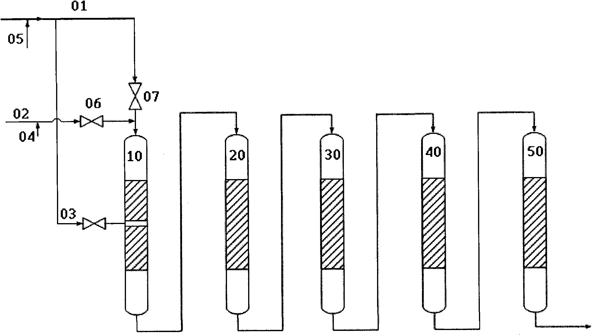
[0066] The same as in Example 1, using a self-designed fixed-bed hydroprocessing test device, the difference is that the device uses four reactors with a volume of 5 liters in series, and the first hydrogenation reaction zone includes two reactors, namely a reaction reactor and reactor b, the second hydrogenation reaction zone includes two reactors, reactor d and reactor e, and a feed line connected to the residual oil raw material pipeline is set at the feed port of reactor e.

[0067] The catalysts used in reactor a, reactor b and reactor d are the same as those in Example 1, and reactor e is filled with hydrodesulfurization catalyst RMS-1 and hydrodesulfurization catalyst RSC-1. Among them, the hydrogenation carbon removal catalyst RSC-1 was developed by the Petrochemical Science Research Institute and produced by Catalyst Changling Branch.

[0068] The loading situation of catalyst in each reactor is:

[0069] In the first hydrogenation reaction zone, the catalysts in the...


PUM


Abstract

The invention provides a hydrogenation method for residual oil. The method includes the following steps: under the condition of hydrogenation reaction, residual oil raw materials and hydrogen gas are sequentially guided into two hydrogenation reaction zones connected in series to carry out contact reaction with a plurality of catalyst beds in the hydrogenation reaction zones; according to the flowing directions of a reactant and the hydrogen gas, the first and second hydrogenation reaction zones respectively comprise a hydrogenation protecting catalyst, a hydrogenation de-metallization catalyst and a hydrogenation desulfurization catalyst which are sequentially filled in the catalyst beds; when the pressure drop of at least one catalyst bed in the first hydrogenation reaction zone reaches the upper limit or hot spots appear in the reaction zone, at least one part of the residual oil raw materials and the hydrogen gas is directly guided into the second hydrogenation reaction zone. Compared with the prior art, the method in the invention can prolong the running period of a residual oil hydrogenation device, thereby increasing the running efficiency of the device and improving the economical property of the device as well.

Description

technical field [0001] The invention relates to a method for hydrogenation of residual oil. Background technique [0002] Residual oil hydrogenation process is a heavy oil deep processing technology. This process is to carry out hydrodesulfurization, hydrodenitrogenation, hydrodemetallization, residual carbon conversion and hydrocracking reactions on residual oil in the presence of hydrogen and catalysts. , the resulting hydrogenated residual oil can be used as a feedstock for high-quality catalytic cracking to produce light oil products, so as to achieve the maximum light weight of residual oil and realize a non-residual oil refinery. [0003] Using hydrotreated residual oil as FCC feed can reduce the sulfur content of FCC gasoline, and at the same time reduce the emission of SOx and NOx in FCC flue gas. Therefore, the processing scheme of residual oil hydrogenation can maximize the light distillate oil, so as to make full use of crude oil resources. [0004] The main rea...

Claims


Application Information

Patent Timeline
IPC IPC(8): C10G65/02
Inventor 邵志才戴立顺牛传峰刘涛杨清河
Owner CHINA PETROLEUM & CHEM CORP
Why Eureka
Try Eureka