
Method and device for light, powder and gas coaxial transmission laser cladding forming manufacturing

A laser cladding, coaxial technology, used in manufacturing tools, laser welding equipment, coatings, etc., can solve the problems of powder beam collimation and rigidity need to be improved, the powder drop area is large, and the powder utilization rate is low. , to reduce the formation of unmelted particles, easy to adjust and control, and improve the utilization rate

Inactive Publication Date: 2010-07-14
SUZHOU UNIV
View PDF3 Cites 31 Cited by
  • Summary
  • Abstract
  • Description
  • Claims
  • Application Information

AI Technical Summary

Problems solved by technology

However, there is a big deficiency in the existing scheme. The trajectory of the powder is a converging-diverging paraboloid. When the powder beam is sprayed out of the powder tube, the powder loses the constraint of the tube wall, and the motion parameters of the powder particles with different particle sizes and shapes will fluctuate. The movement trajectory and landing point of the powder particles in the air will also be inconsistent, which will result in a large range of powder particle drop areas, difficult to stabilize the convergence accuracy, poor rigidity of the powder beam, and easy divergence
The shielding gas 1 sprayed from the middle of the powder diffuses the powder beam outward, while the shielding gas 5 diffuses the powder beam inward, so there is a problem of pressure coordination between the double-layer shielding gas, its size adjustment control is very sensitive, and it is difficult to accurately converge the powder beam
Due to the unstable amount of powder entering the molten pool, the powder sprayed next to the molten pool is not melted or not penetrated after the molten pool solidifies, causing physical and geometric defects on the formed surface
Cladding practice has proved that the airflow formed by the double-layer shielding gas near the nozzle is generally turbulent, and the powder splashes around during processing, the powder utilization rate is extremely low, and the environmental pollution is great
[0004] In view of the above-mentioned deficiencies, the applicant once disclosed in Chinese patent CN200610116413.1 a laser processing and forming manufacturing optical internal powder feeding process and an optical internal powder feeding nozzle, which realized the hollow focused laser beam internal powder feeding and improved the coupling of light and powder. accuracy, but it does not involve the transmission method of the shielding gas, and the relationship between the shielding gas, the focused laser beam, and the powder beam; the powder still diverges after being sprayed out of the powder nozzle; the collimation and rigidity of the powder beam need to be determined. improve

Method used


Image

  • Method and device for light, powder and gas coaxial transmission laser cladding forming manufacturing
  • Method and device for light, powder and gas coaxial transmission laser cladding forming manufacturing
  • Method and device for light, powder and gas coaxial transmission laser cladding forming manufacturing

Examples


Embodiment 1

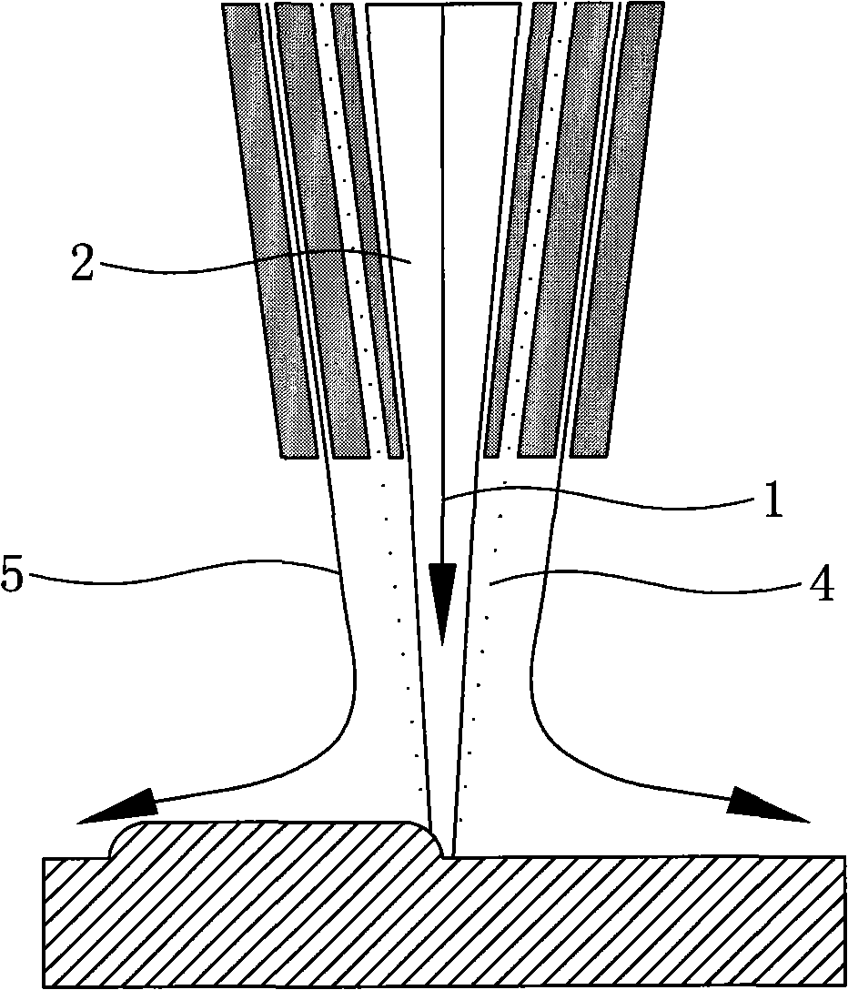
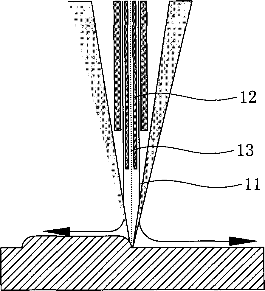
[0024] Embodiment one: see Figures 2 to 4 As shown, a laser cladding manufacturing method for coaxial transmission of light, powder and gas, transforms and expands the circular cross-section solid laser beam emitted by the laser through optical path conversion, and then becomes a circular laser beam. The circular laser beam is focused to become a hollow circular conical focused laser beam, and a powder spray nozzle is arranged in the hollow part of the circular conical focused laser beam, and the powder spray nozzle is coaxial with the circular conical focused laser beam line; a circle of collimated protective gas curtain is arranged on the periphery of the single powder beam ejected from the powder spray nozzle, and the collimated protective gas curtain is connected with the circular conical focused laser beam and the single powder beam sprayed from the powder spray nozzle. The air pressure of the collimated protective air curtain is 0.1-0.5Mpa.

[0025] A light, powder, an...

Embodiment 2

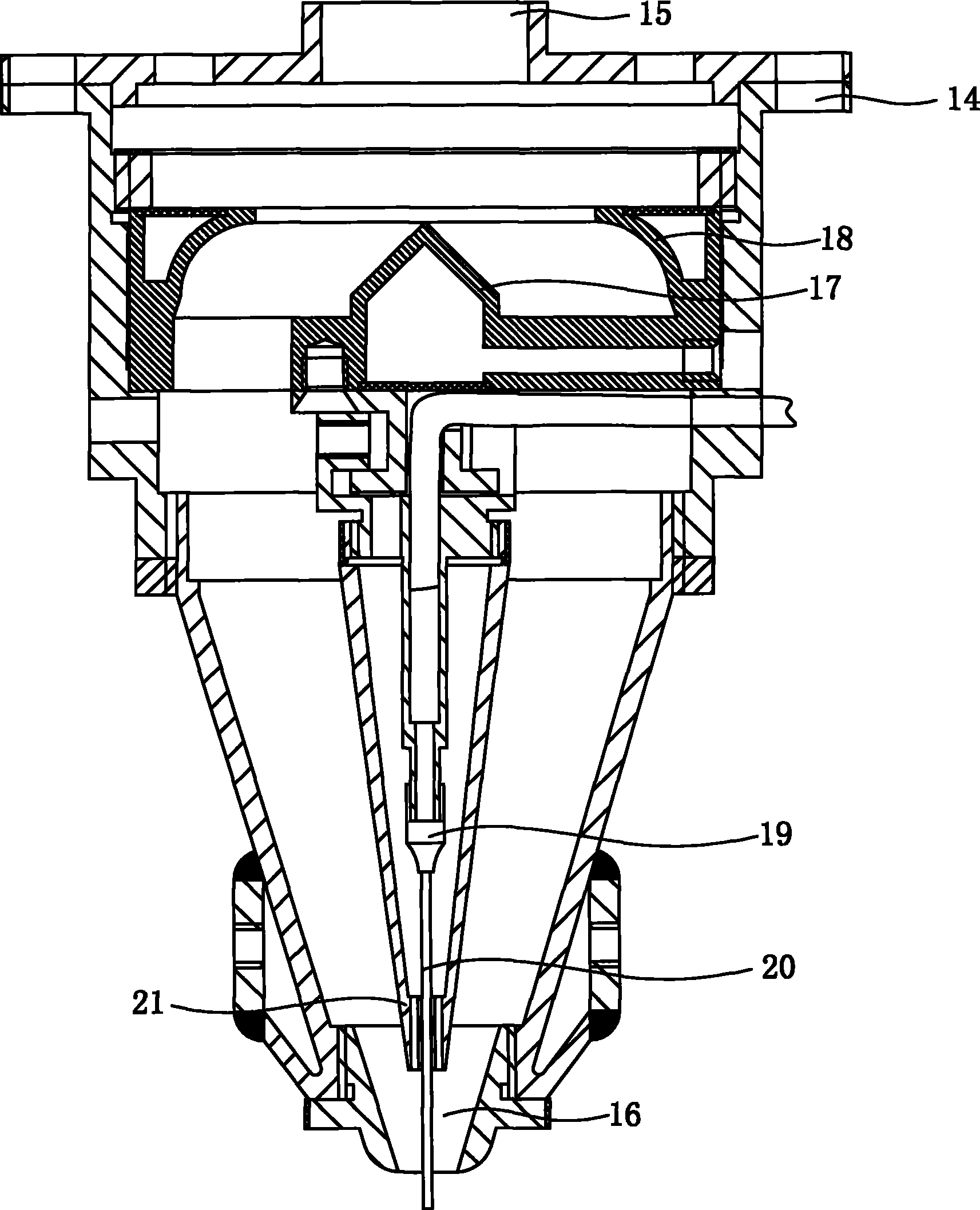
[0027] Embodiment two: see Figure 5 As shown, a device for coaxially conveying light, powder, and gas to laser cladding and forming manufacturing includes a powder feeding nozzle cylinder, a light inlet is opened on the top of the cylinder, and a light outlet is opened below the cylinder. There is a conical reflector facing the light entrance in the body, and a circular reflective focusing mirror is arranged coaxially with the conical reflector. A powder feeding tube is fixed below the conical reflector, and the lower end of the powder feeding tube is A powder spray nozzle 20 is provided, the powder spray nozzle is coaxial with the laser beam, and the outer periphery of the powder spray nozzle 20 is provided with a collimating protective air jacket 21 between the conical reflector and the exit of the powder spray nozzle 20. The collimation protection air jacket 21 is provided with three arc-shaped air outlets 22 along the circumferential direction. The axis of the powder spr...


PUM


Abstract

The invention discloses a method for light, powder and gas co-axial transmission laser cladding forming manufacturing, which is characterized in that: a circular section solid laser beam emitted by a laser is subjected to transformation and beam expansion by the optical path transformation to become a circular laser beam; the circular laser beam is focused to become a hollow circular cone focused laser beam; a powder spraying nozzle is arranged on the hollow part of the circular cone focused laser beam; the powder spraying nozzle and the circular cone focused laser beam are coaxial; the periphery of a single powder beam sprayed by the powder spraying nozzle is provided with a circle of collimation shielding gas curtain; and the collimation shielding gas curtain, the circular cone focused laser beam and the single powder beam sprayed by the powder spraying nozzle are coaxial. By arranging the collimation shielding gas curtain on the periphery of the powder beam, the method realizes the coaxial transmission of light, powders and gas and solves the defects in the prior art.

Description

technical field [0001] The invention relates to the field of laser processing and forming, in particular to a method and device for coaxially conveying light, powder and gas to produce laser cladding and forming. Background technique [0002] In the prior art, the simultaneous powder feeding laser cladding forming of metal materials is completed by a special laser cladding nozzle, the method and structure of which are disclosed in European Patent WO2005028151 and Japanese Patent JP2005219060. The basic principle is that the beam is centered and the metal powder is surrounded and conveyed: the cylindrical laser beam emitted by the laser is focused into a solid conical laser beam, the processing surface is placed near the focus, and multiple relative beam axes are arranged around the solid conical laser beam With the inclined powder spraying nozzle, the converging point of the multiple powder beams ejected from the multiple powder spraying nozzles is just placed near the focal...

Claims


Application Information

Patent Timeline
IPC IPC(8): B23K26/14C23C24/10
Inventor 傅戈雁石世宏郭开波刘秀波孙承峰
Owner SUZHOU UNIV
Learn More