Pressure resistance detecting device for petroleum underground tool
A detection device and technology for oil wells, which are applied in the direction of using liquid/vacuum for liquid tightness measurement, measurement, wellbore/well components, etc., can solve the problems of high cost, long test period, complex system, etc., and achieve low cost , the test cycle is short, the effect of ensuring personal safety
- Summary
- Abstract
- Description
- Claims
- Application Information
AI Technical Summary
Problems solved by technology
Method used
Image


Examples
Embodiment 1
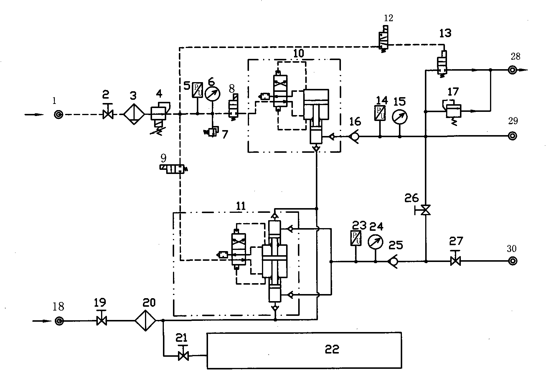
[0023] Such as figure 2 As shown, both ends of the downhole tool have water inlet and outlet interfaces, wherein one end of the downhole tool (31) is connected to the low-pressure water outlet interface (30), and the other end is connected to the high-pressure water outlet interface (29). Before the test, first raise the end of the downhole tool (31) connected to the high-pressure water outlet interface (29), then open the gas circuit shut-off valve (2), water shut-off valve (19), high-pressure shut-off valve (27), and close the water shut-off valve (21) and high pressure shut-off valve (26).
[0024] The test process is as follows: After the compressed air is introduced from the air inlet (1), it passes through the air circuit stop valve (2) and the air filter (3), and then is decompressed to the set value by the proportional pressure reducing valve (4) controlled by the computer. , the computer sends a signal to connect the electromagnetic reversing valve (9), the compress...
Embodiment 2
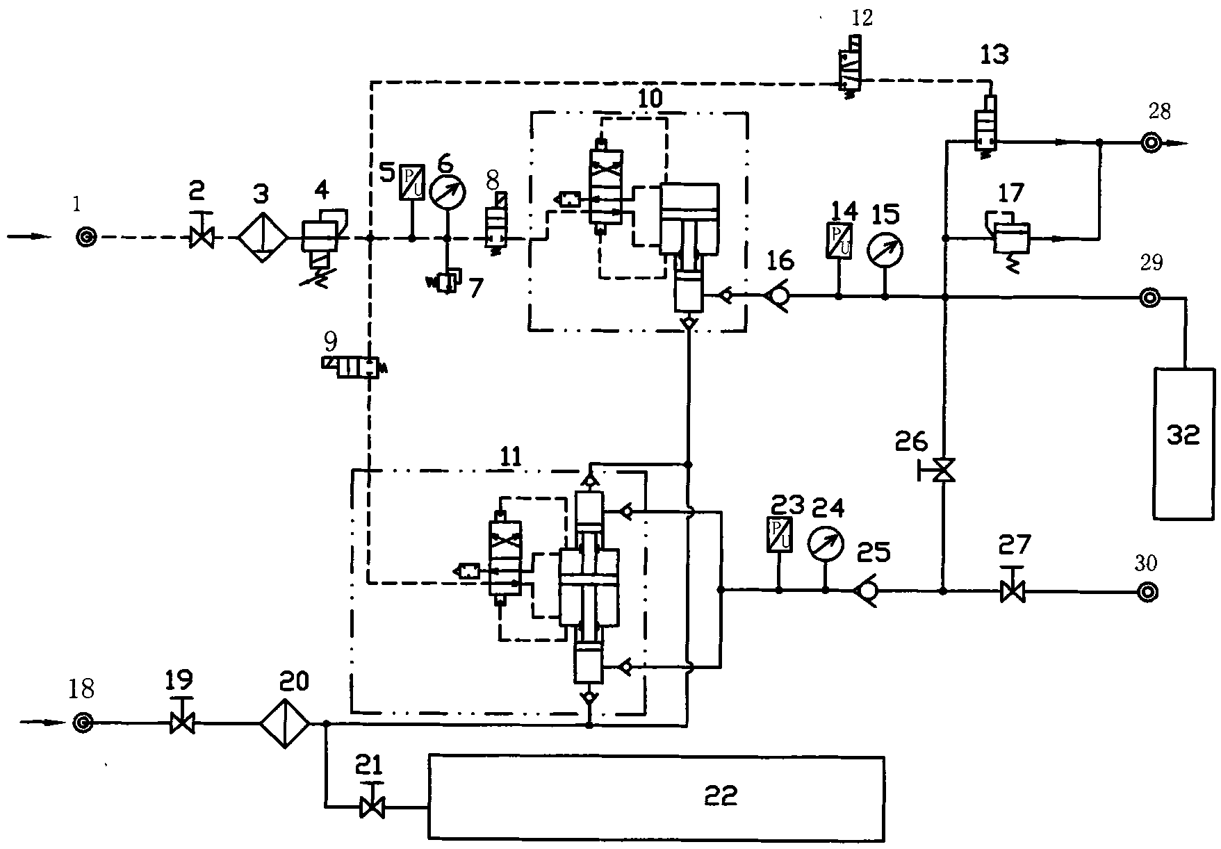
[0026] Such as image 3 As shown, only one end of the downhole tool has a water inlet and outlet interface. Before the test, first raise one end of the downhole tool (32) connecting pipe to facilitate the discharge of air, and then open the gas shut-off valve (2), water shut-off valve (19), high pressure Stop valve (26), close water stop valve (21), high pressure stop valve (27).
[0027] The test process is as follows: After the compressed air is introduced from the inlet (1), it passes through the air circuit stop valve (2) and the air filter (3), and then is decompressed to the set value by the proportional pressure reducing valve (4) controlled by the computer. The computer sends a signal to energize the electromagnetic reversing valve (9), and the compressed air enters the low-pressure air-driven liquid pump (11). The high-pressure water shut-off valve (26) is injected from the interface of the tool to be tested at last, and this process is a water injection process. Du...
Embodiment 3
[0029] Such as Figure 4 Shown is the flow chart of the fully automatic test control module, combined below figure 2 , image 3 and Figure 4 to explain its working process.
[0030] The working process of the fully automatic test control module is as follows: first, initialize the settings through the computer, including setting the gas drive pressure P0, low pressure P1, high pressure P2, number of water inlet N, pressure holding time T1, single head exhaust times M, Double head exhaust time T2. After the initialization is completed, the pressure of the proportional pressure reducing valve (4) is adjusted according to the set value of P0, and after reaching the set value, the number of water inlet heads N is judged. N=1 is single water inlet (such as image 3 shown), N=2 for double-headed water inlet (such as figure 2 shown). When N=1, the electromagnetic reversing valve (9) is energized, the electromagnetic reversing valve (12) is de-energized, water injection is s...
PUM
 Abstract
Description
Claims
Application Information
 - R&D
- Intellectual Property
- Life Sciences
- Materials
- Tech Scout
- Unparalleled Data Quality
- Higher Quality Content
- 60% Fewer Hallucinations
Browse by: Latest US Patents, China's latest patents, Technical Efficacy Thesaurus, Application Domain, Technology Topic, Popular Technical Reports.
© 2025 PatSnap. All rights reserved.Legal|Privacy policy|Modern Slavery Act Transparency Statement|Sitemap|About US| Contact US: help@patsnap.com