
Liquid-crystal display device
A technology of liquid crystal display device and liquid crystal layer, applied in optics, instruments, nonlinear optics, etc., can solve the problems of reduced production adaptability and difficulty in realization
- Summary
- Abstract
- Description
- Claims
- Application Information
AI Technical Summary
Problems solved by technology
Method used
Image

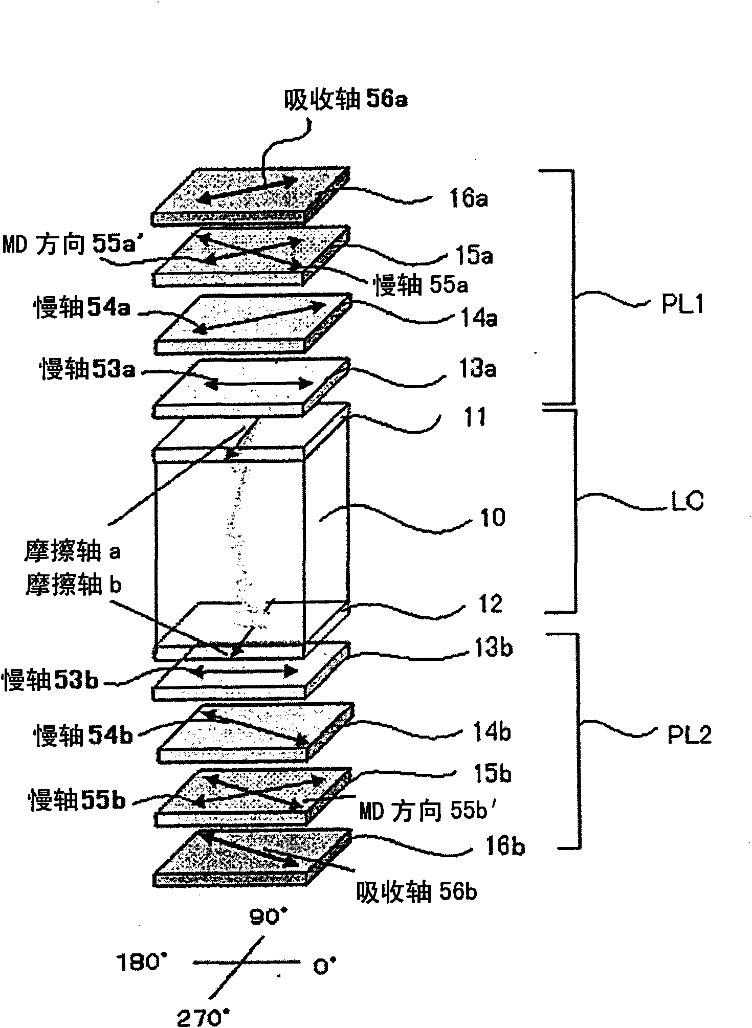
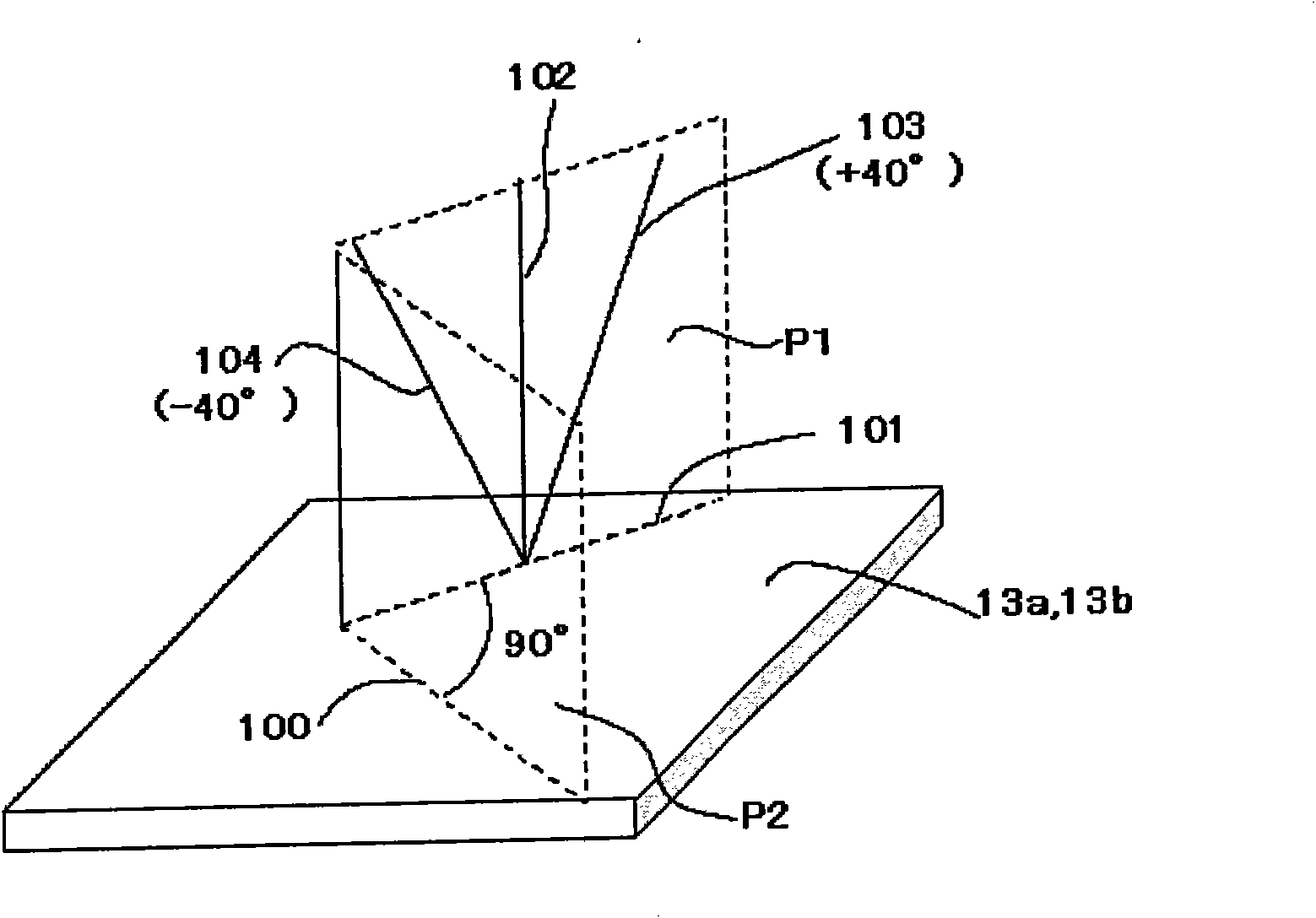
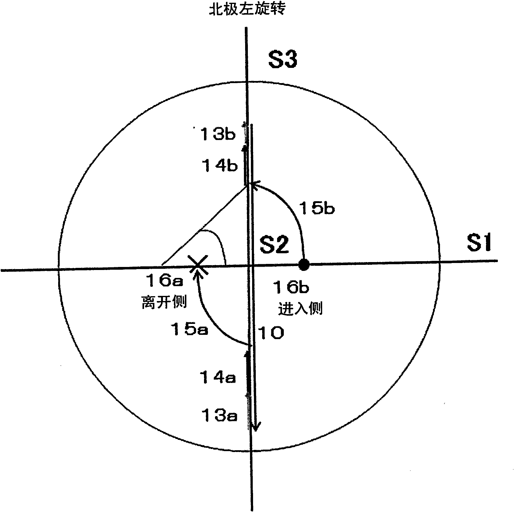
Examples
preparation example Construction
[0238] "Preparation method of roll optical film"
[0239] The optical film can be prepared according to the continuous process of the following steps (1) to (4):
[0240] Step (1): A long continuous polymer film for at least the second optically anisotropic layer is conveyed in the length direction while rubbing the surface of the film or the surface of an alignment film formed on the film surface with a rubbing roll.
[0241] Step (2): Applying a liquid crystal compound-containing coating liquid onto the rubbed surface.
[0242] Step (3): drying the coating liquid coated on the surface, while or after drying, orienting the molecules of the liquid crystal compound at a temperature not lower than the liquid crystal transition temperature of the liquid crystal compound, and fixing the orientation to form the first optical each Anisotropic layer.
[0243] Step (4): Winding up a long and continuous optical film in which the first optically anisotropic layer is formed on the poly...
Embodiment 1
[0331] 1.-1 Formation of the third optically anisotropic layer
[0332]
[0333] Cellulose acetate solution A was prepared by placing the following components in a mixing tank, stirring under heating, and dissolving each component.
[0334] Composition of Cellulose Acetate Solution A
[0335] ・100 parts by mass of cellulose acetate with a degree of acetylation of 60.9%
[0336] 7.8 parts by mass of triphenyl phosphate
[0337] 3.9 parts by mass of biphenyl diphenyl phosphate
[0338] 300 parts by mass of dichloromethane
[0339] 45 parts by mass of methanol
[0340]4 parts by mass of cellulose acetate with an acetylation degree of 60.9% (lint), 25 parts by mass of the retardation enhancer shown below, 0.5 parts by mass of silica fine particles (average particle diameter: 20 nm), 80 parts by mass of Dichloromethane and 20 parts by mass of methanol were put into another mixing tank and stirred under heating to prepare a retardation enhancer solution.
[0341] Latency Enh...
Embodiment 2~9
[0417] An OCB mode liquid crystal display device was prepared and evaluated in the same manner as in Example 1, however, the TAC film used as the second optically anisotropic layer was replaced with a TAC film having properties shown in Table 1 and / or used as the third optically anisotropic layer. Anisotropic layer of TAC film.
[0418] The Re and Rth of the TAC film were controlled by changing the conditions of the biaxial stretching treatment.
PUM
| Property | Measurement | Unit |
|---|---|---|
| phase transition temperature | aaaaa | aaaaa |
| saponification | aaaaa | aaaaa |
| saponification | aaaaa | aaaaa |
Abstract
Description
Claims
Application Information