Jet control system utilizing air-assisted power to atomize urea reductant

An air-assisted and control system technology, applied in the direction of exhaust devices, engine components, machines/engines, etc., can solve the problems of SCR conversion efficiency drop, blockage, etc., and achieve the effects of easy industrial application, elimination of NOX, and high reliability

Inactive Publication Date: 2010-08-04
FAW GROUP
View PDF6 Cites 12 Cited by
  • Summary
  • Abstract
  • Description
  • Claims
  • Application Information

AI Technical Summary

Problems solved by technology

However, when the engine is running at a cold start, idling or insufficient combustion stage, the temperature is usually kept below 150°C. At this time, more HC and PM can be generated. These components can block the microscopic pores of the SCR catalyst, resulting in SCR conversion efficiency drops

Method used


Image

  • Jet control system utilizing air-assisted power to atomize urea reductant
  • Jet control system utilizing air-assisted power to atomize urea reductant

Examples


Embodiment 1

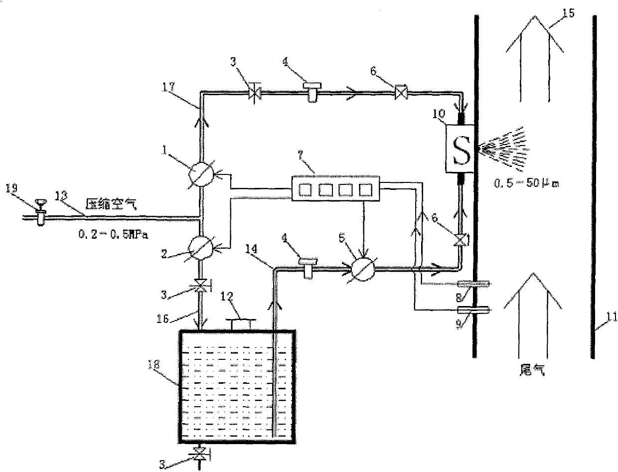
[0024] Use a stainless steel tube or nylon tube with an inner diameter of 10mm as the compressed air main pipe 13. The pressure range of the compressed air main pipe 13 is 0.2Mpa, which is preset by the pressure regulating valve 19. The power source of the compressed air can come from the brake air storage tank on the vehicle; Stainless steel pipes with an inner diameter of 4 mm are used as the urea reducing agent delivery pipe 14, the compressed air branch pipe 16 of the urea reducing agent storage tank and the nozzle atomization compressed air branch pipe 17; adjust the pressure range of the nozzle atomization compressed air branch pipe 17 to 0.1Mpa; adjust the urea reducing agent storage The pressure range of the tank compressed air branch pipe 16 is 0.14Mpa; the opening of the liquid flow solenoid valve 5 is adjusted by the signal output by the control unit 7; the input signal of the control unit 7 comes from the industrial temperature sensor 8; the pressure-resistant urea r...

Embodiment 2

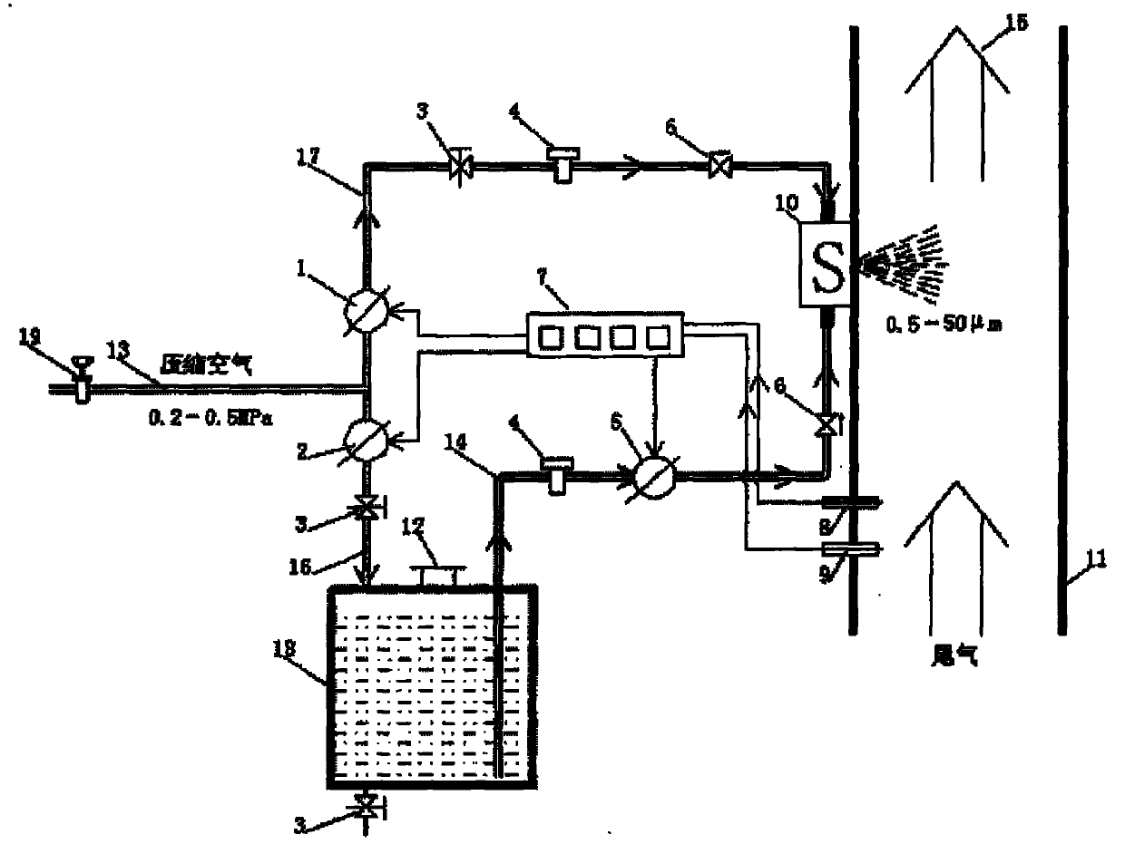
[0026]A nylon tube with an inner diameter of 10mm is used as the compressed air main pipe 13. The pressure range of the compressed air main pipe 13 is 0.5Mpa, which is preset by the pressure regulating valve 19. The power source of the compressed air can come from the vehicle-mounted brake air tank; the inner diameter is 6mm The nylon tube is used as the urea reducing agent delivery pipe 14, the compressed air branch pipe 16 of the urea reducing agent storage tank, and the nozzle atomizing compressed air branch pipe 17; adjust the pressure range of the nozzle atomizing compressed air branch pipe 17 to 0.4Mpa; adjust the compressed air of the urea reducing agent storage tank The pressure range of the branch pipe 16 is 0.46Mpa; the opening degree of the liquid flow solenoid valve 5 is regulated by the signal output by the control unit 7; the input signal of the control unit 7 comes from an industrial temperature sensor 8; the pressure-resistant urea reducing agent container cover ...


PUM


Abstract

The invention relates to a jet control system utilizing air-assisted power to atomize urea reductant, which is characterized in that the air inlet end of a compressed air main pipe is provided with a pressure regulating valve, the air outlet end thereof is respectively communicated with a compressed air branch pipe for a blowing nozzle and a urea reductant storage tank compressed air branch pipe; the urea reductant storage tank compressed air branch pipe is connected on a urea reductant container; the compressed air branch pipe for the blowing nozzle is communicated with a single-cavity urea reductant nozzle, one end of a urea reductant delivery pipe is arranged in the urea reductant container, the other end thereof is communicated with the urea reductant nozzle, and a temperature sensor arranged on the exhaust pipe of an engine and a nitric oxide sensor are electrically connected with a control unit. The temperature measured by a cheap industrial thermocouple with very high reliability is taken as a main control parameter to control urea flow, thus urea reductant can be fully atomized in a two-cavity hybrid unit, while the cost is equivalent to 1/2-1/3 of an imported system. The system has high reliability, and is easy to realize industrialized application by depending on resources in China.

Description

Technical field: [0001] The invention relates to an air-assisted power atomization urea reducing agent injection control system, which is applied in the automobile engine industry and meets the environmental protection requirements above Euro 4. Background technique: [0002] The harmful components in automobile engine exhaust are mainly PM, NOX, HC and CO. In the past 2 to 3 years, low-emission engines have become an ideal that people debate, care about, and even aspire to achieve. [0003] The U.S. Environmental Protection Agency (EPA) 2007 emissions regulations require automakers to reduce both particulate (PM) and nitrogen oxide (NOX) pollutants in exhaust gases. This requires considerable skill, and there are no shortcuts to solving this problem. According to the traditional method, the reduction of one kind of pollution will inevitably lead to the increase of another kind of pollution. Automakers appear to be in trouble. [0004] Under the pressure of emission regu...

Claims


Application Information

Patent Timeline
Patent Type & Authority Applications(China)
IPC IPC(8): F01N3/18
Inventor 张克金王丹魏晓川崔龙张苡铭刘国军董鹤维
Owner FAW GROUP
Why Eureka
Try Eureka