High-pressure transducer testing system

A high-voltage frequency converter and test system technology, which is applied in the direction of instruments, measuring electronics, and measuring devices, can solve problems such as unsafe test efficiency and low efficiency, and achieve the effects of improving test efficiency, reducing energy consumption, and ensuring test safety

Active Publication Date: 2010-08-04
SHANGHAI STEP ELECTRIC +1
View PDF5 Cites 18 Cited by
  • Summary
  • Abstract
  • Description
  • Claims
  • Application Information

AI Technical Summary

Problems solved by technology

[0004] The technical problem to be solved by the present invention is to overcome the defects of unsafe and low test efficiency of the existing high-voltage frequency converter test system, and provide a cascaded high-voltage frequency converter that can safely, efficiently and conveniently develop and debug high-voltage frequency converters device test system

Method used


Image

  • High-pressure transducer testing system
  • High-pressure transducer testing system
  • High-pressure transducer testing system

Examples


Embodiment 1

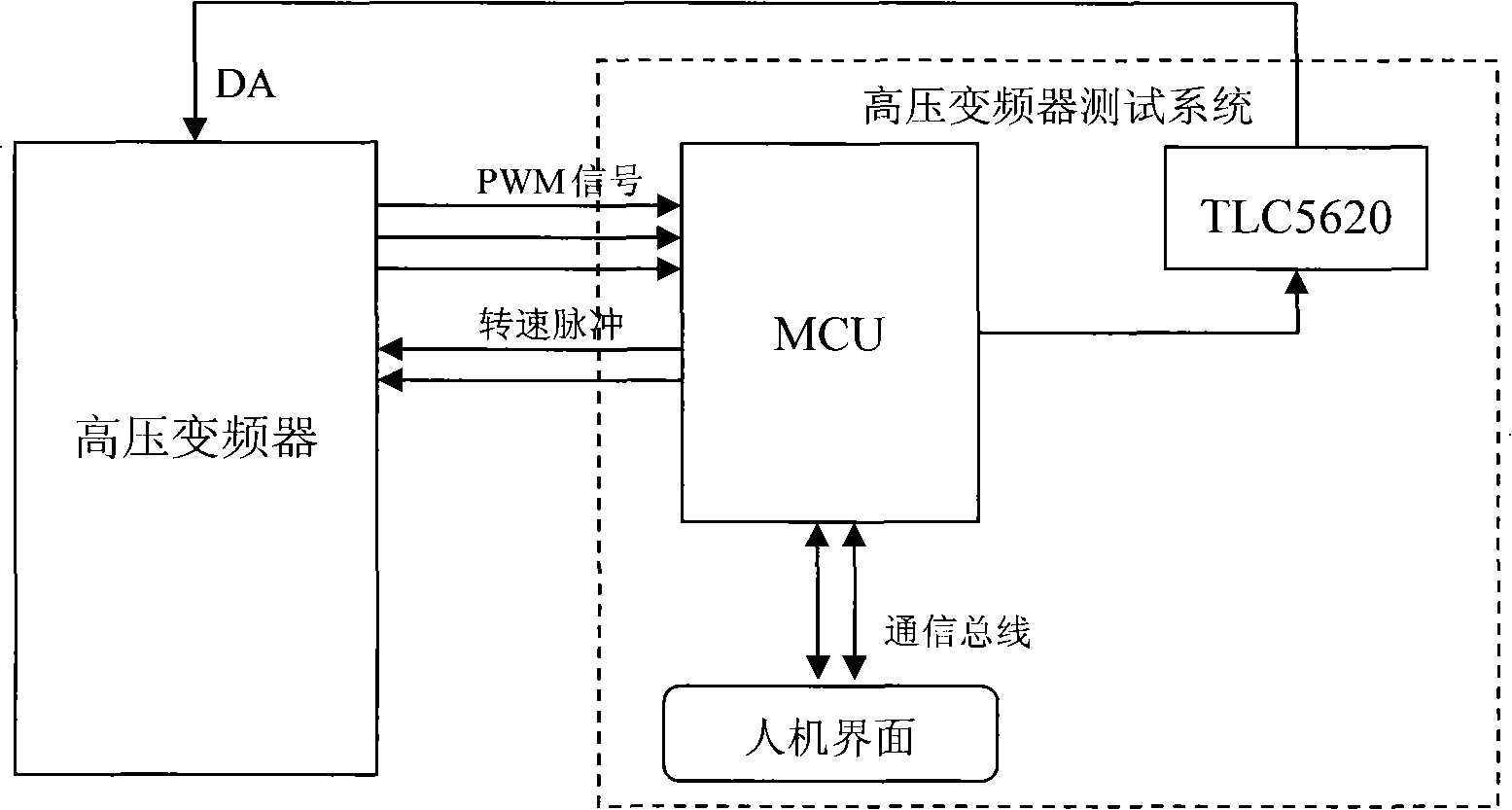
[0039] Such as figure 2 Shown is a high-voltage inverter test system based on MCU chips. In this embodiment, a high-performance MCU chip (STM32F103VB type) is selected to simultaneously realize functions such as PWM detection module, power unit module, motor module, and speed pulse output. Select D / A conversion chip, such as TLC5620 chip, to realize D / A output function. Users can use the man-machine interface to set the status of various peripheral components and system environment parameters through the communication module of the system, and can also simulate various fault sources. The MCU chip detects the PWM wave output by the high-voltage inverter in real time and at high speed through the I / O parallel port interrupt. At the same time, according to the PWM detection result and the motor model parameters, the output voltage, current, speed, torque, power value and other physical quantities can be calculated. Then, by driving the D / A chip, the physical quantities such as vo...

Embodiment 2

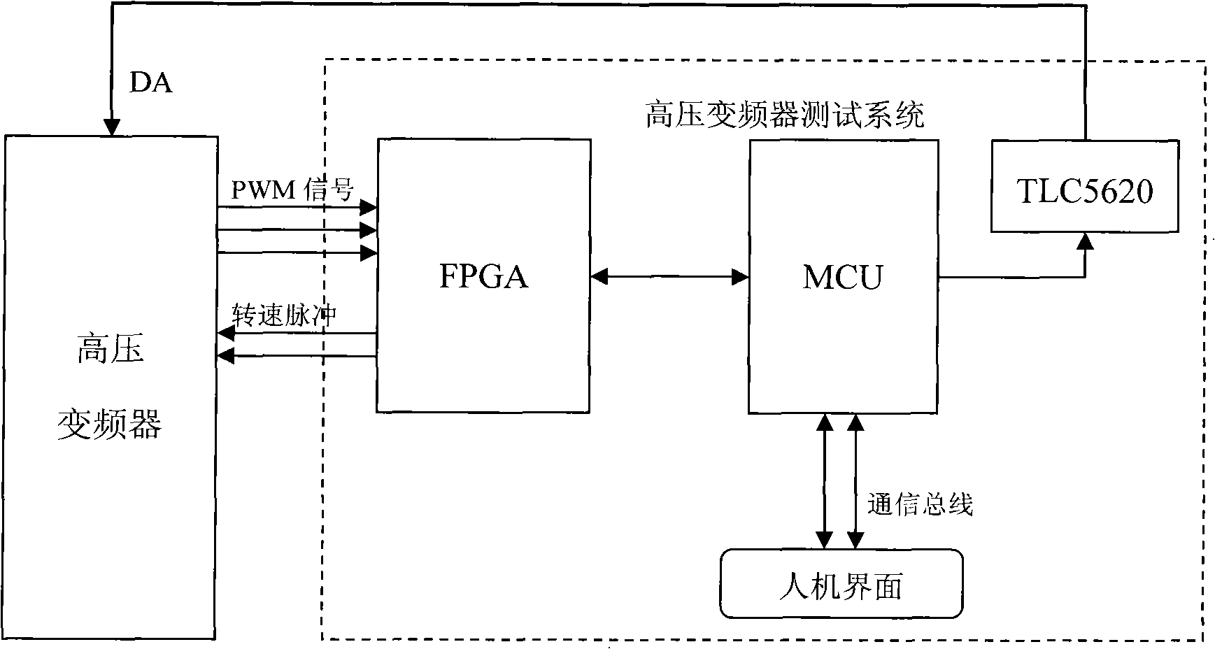
[0041] Such as image 3 Shown is a high-voltage inverter test system based on FPGA+MCU. This embodiment FPGA chip selects the A3P250 type chip of ProASIC3 series, and it realizes PWM wave detection module, power unit module function, promptly is used for being responsible for PWM wave detection, superimposes frequency converter output voltage, and the result of detection and processing passes through I / O parallel port and I 2 The C interface is transmitted to the MCU chip, and the encoder is simulated at the same time, and the real-time speed calculated by the MCU chip is output in the form of pulses. The MCU chip uses STM32F103VB chip, which realizes the function of the motor module, through the I / O parallel port or I 2 The C interface reads the PWM detection and processing results transmitted by the FPGA chip, and calculates the physical quantities such as voltage, current, speed, torque, and power in real time. At the same time, physical quantities such as voltage and c...


PUM


Abstract

The invention discloses a high-pressure transducer testing system which comprises an upper computer part and a lower computer part electrically connected with a high-pressure transducer. The upper computer part comprises a human-computer interface module and a PLC (Programmable Logic Controller) module, and the lower computer part comprises a power unit module, a motor module, an input side module and an output side module which are sequentially and electrically connected. The testing system can universally support the debugging and the testing of the high-pressure transducer in the development process of the high-pressure transducer and directly detect the control algorithm and the effect of the high-pressure transducer to further ensure the testing safety, improve the testing efficiency and reduce the energy consumption.

Description

technical field [0001] The invention relates to a test system, in particular to a cascaded high-voltage frequency converter debugging technology. Background technique [0002] Due to the characteristics of the high-voltage inverter itself, the difficulty in the development process is increased. For example, running in a high-pressure environment increases the difficulty of debugging and testing during the development process due to safety considerations. At the same time, the potential defects of the system are also very likely to cause greater material damage. The high-voltage inverter has many and large components. It takes a long time from the production of the cabinet and the procurement of related components to the final assembly and debugging, which delays the test time of the project and makes it difficult to conduct a comprehensive test of the system. [0003] In the current process of developing high-voltage inverters, the main test method is to customize a small ...

Claims


Application Information

Patent Timeline
Patent Type & Authority Applications(China)
IPC IPC(8): G01R31/00G01R19/25
Inventor 李兴鹤宋吉波马艳玲时迎亮吴芸谢海峰邢辉李唯为
Owner SHANGHAI STEP ELECTRIC
Why Eureka
Try Eureka