
Method for calculating signal-to-noise ratio (SNR) of magnetic resonance imaging (MRI) RF coil

A magnetic resonance imaging, signal-to-noise ratio technology, applied in computing, special data processing applications, instruments, etc., can solve problems such as unfavorable coil structure optimization, reduced computing efficiency, and increased subsections

Inactive Publication Date: 2010-08-04
TSINGHUA UNIV
View PDF0 Cites 10 Cited by
  • Summary
  • Abstract
  • Description
  • Claims
  • Application Information

AI Technical Summary

Problems solved by technology

When using the finite element method to calculate the equivalent noise resistance of the coil, in order to determine the boundary conditions, it is necessary to increase the air domain, resulting in an increase in the subdivision component and a decrease in calculation efficiency, which is not conducive to the optimization of the coil structure

Method used


Image

  • Method for calculating signal-to-noise ratio (SNR) of magnetic resonance imaging (MRI) RF coil
  • Method for calculating signal-to-noise ratio (SNR) of magnetic resonance imaging (MRI) RF coil
  • Method for calculating signal-to-noise ratio (SNR) of magnetic resonance imaging (MRI) RF coil

Examples


Embodiment Construction

[0057] The principle and specific implementation of the present invention will be described below in conjunction with the accompanying drawings.

[0058] Example (Torus Surface Coil):

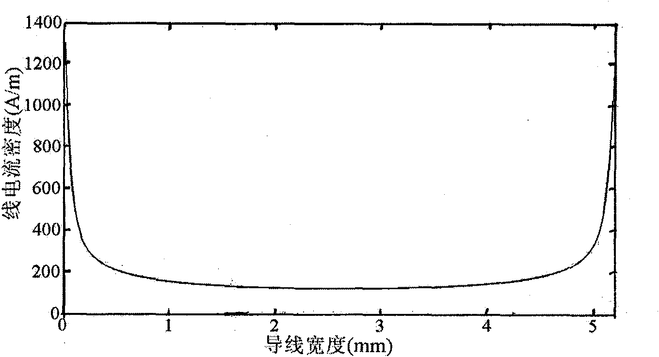
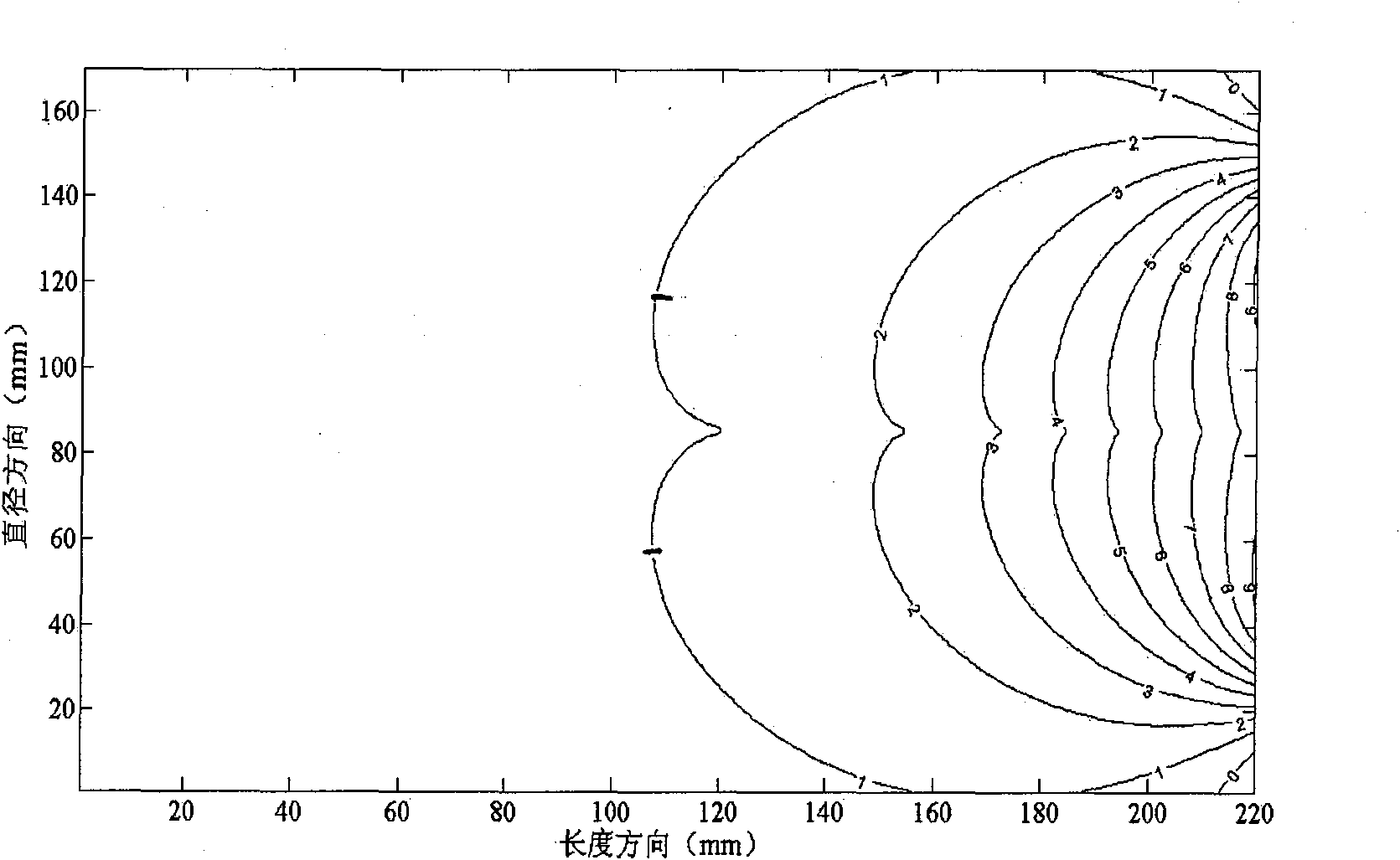
[0059] The coil is a circular coil with a radius of 62.1mm, and the cross-section of the conductor is a rectangle with a width of 5.2mm and a thickness of 0.2mm. Conductor material is copper strip, magnetic permeability is 4π×10 -7 H / m, the measured conductivity is 5.294×10 7 S / m. The load is a cylinder with a length of 22 cm and a diameter of 17 cm, with a conductivity of 0.8 S / m. The coil is 2 cm below the load. A current of radio frequency f=14.85MHz is passed through the coil. A. Calculate the equivalent resistance of the coil; B. Calculate the SNR of the coil.

[0060] (1) Determine the size and material properties of the coil and load according to the actual situation.

[0061] (2) According to the quasi-steady-state assumption, the integral equation satisfied by the current densit...


PUM


Abstract

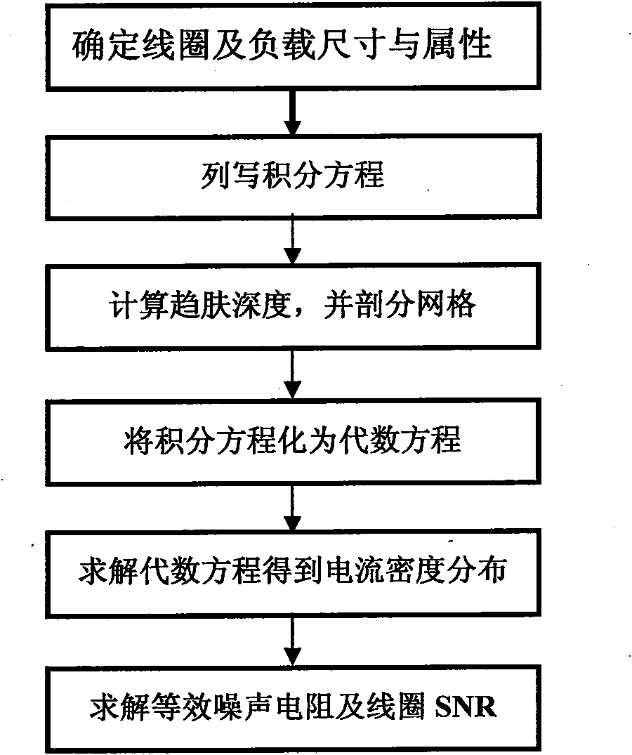
The invention discloses a method for calculating a signal-to-noise ratio (SNR) of a magnetic resonance imaging (MRI) RF coil, belonging to the technical field of magnetic resonance imaging (MRI), which is characterized by comprising the following steps: constructing an RF coil and a load size and material parameter model, listing integral equations satisfied by current densities, calculating skin depth and surface resistivity of a conductor and dissecting the conductor on the basis, converting the integral equations into algebraic equations, solving the algebraic equations to obtain current density distribution in the conductor, calculating magnetic flux density distribution in the load by using Biot-Savart integral, and adopting vector potential to obtain electric field strength distribution in the load, thus calculating self resistance, load eddy-current loss equivalent resistance and SNR of the RF coil. The invention improves the calculation efficiency of self resistance, load eddy-current loss and electric magnetic field space distribution of the conductor.

Description

technical field [0001] The invention belongs to the field of electromagnetic field finite element analysis, in particular to the design of a magnetic resonance imaging (MRI) radio frequency receiving coil. Background technique [0002] Magnetic resonance imaging (MRI) is a technique that uses the phenomenon of nuclear magnetic resonance for imaging. As the receiving antenna of the resonance signal, the performance of the radio frequency receiving coil has a direct impact on the imaging quality of the MRI system. The signal-to-noise ratio (SNR, Signal to Noise Ratio), resolution and imaging speed of an MRI image largely depend on the SNR of the radio frequency receiving coil. The SNR of the coil can be defined as [0003] SNR = B R eff [0004] Among them, B is the effective value of the magnetic induction intensity generated at this point when the radio frequency coil passes...

Claims


Application Information

Patent Timeline
IPC IPC(8): G06F17/50
Inventor 李烨蒋晓华
Owner TSINGHUA UNIV
Learn More