

Method for thermal deformation error compensation of digital control gear hobbing machine
A technology of thermal deformation error and compensation method, which is applied in the direction of manufacturing tools, other manufacturing equipment/tools, etc., can solve the problem that the establishment of error compensation model is not practical, does not involve the mathematical modeling and compensation method of machine tool thermal error, CNC machine tools The positioning and trajectory tracking accuracy of the feed system is not high
- Summary
- Abstract
- Description
- Claims
- Application Information
AI Technical Summary
Problems solved by technology
Method used
Image

Examples
Embodiment
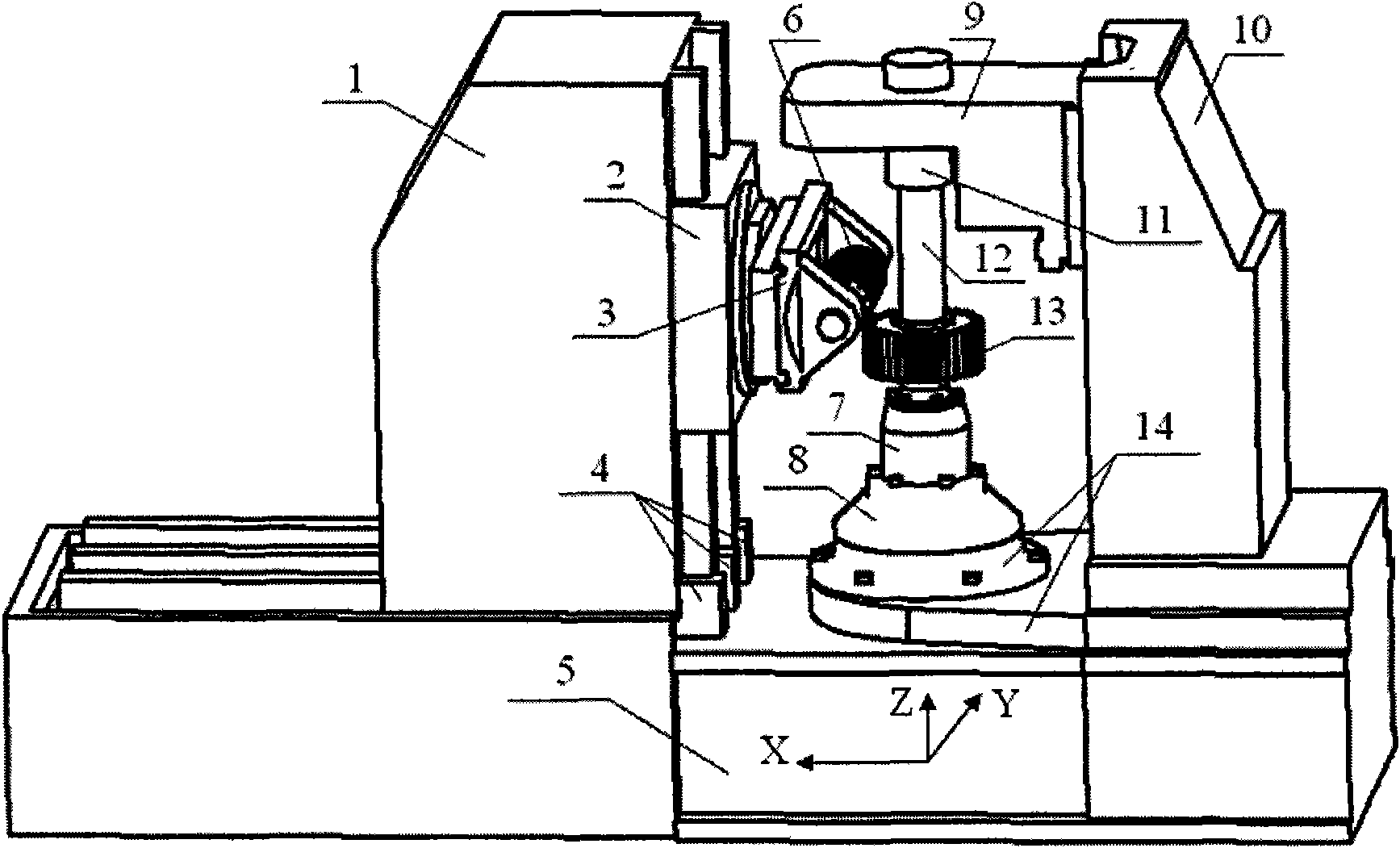
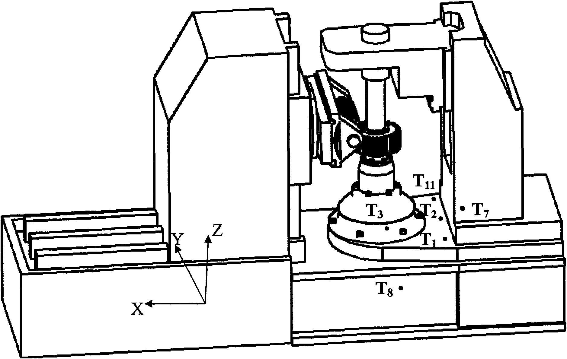
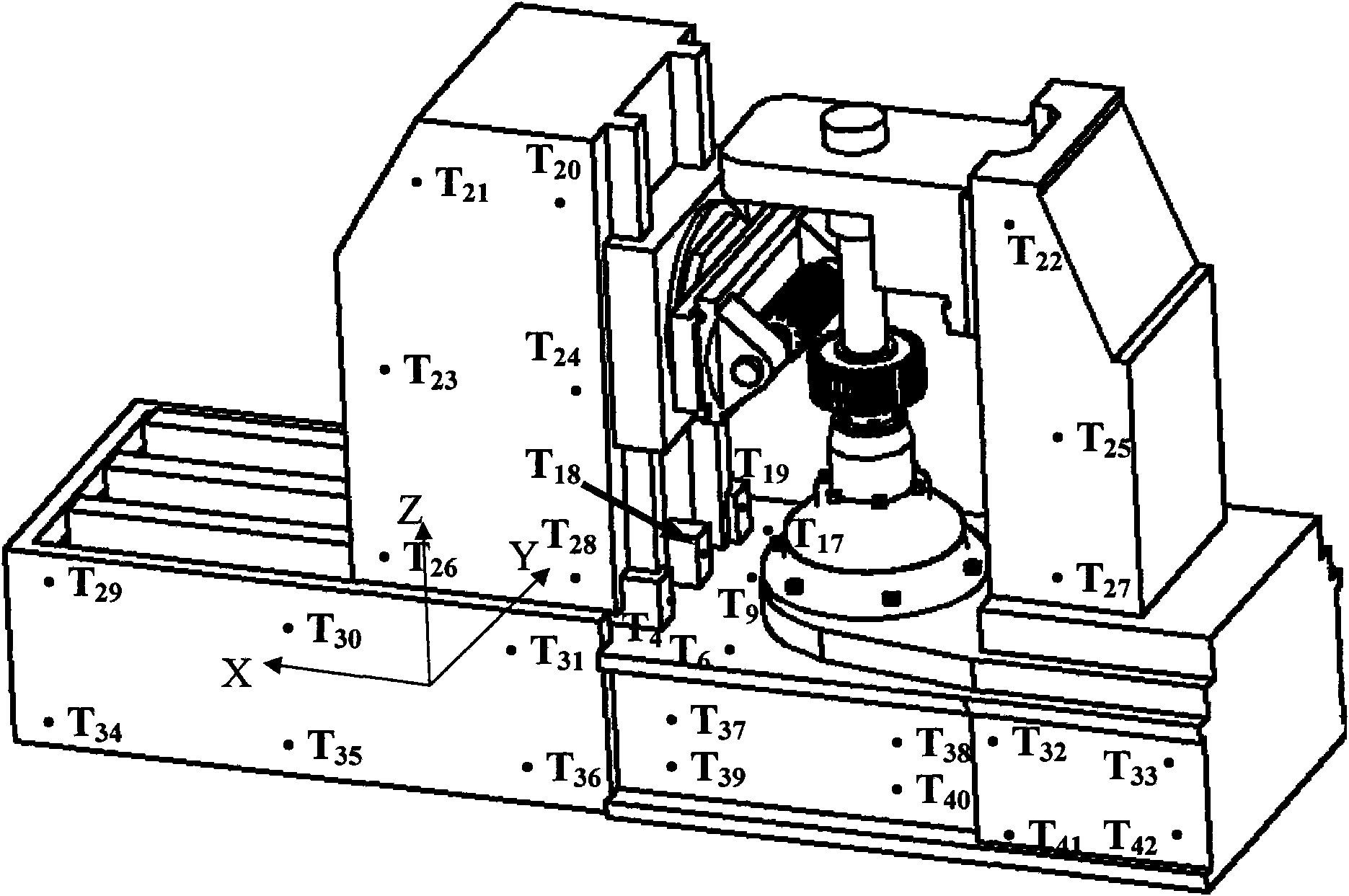
[0100] The following is an example of thermal deformation error compensation using the model YKS3120 CNC gear hobbing machine:
[0101] 1) if figure 2 , image 3 , Figure 4 , Figure 5 , Figure 6 , Figure 7 and Figure 8 As shown, 64 temperature sensors T are arranged in the machining area of CNC gear hobbing machine model YKS3120 1 , T 2 , T 3 ,...,T 64 and 7 displacement sensors X 1 、X 2 ,...,X 7 (X 1 with X 2 is the thermal deformation displacement value in the radial X direction of the hob spindle, X 3 、X 4 、X 5 、X 6 , and X 7 is the thermal deformation displacement value in the radial X direction of the working mandrel), online measurement of temperature and thermal deformation displacement, the measurement time is 12 hours, and a set of data is read in 30 seconds;
[0102] 2) Figure 9 is the temperature variable-time variation curve optimized for modeling, where the optimized set of temperature variables: {T 1 , T 3 , T 5 , T 10 , T 12 , T...
PUM
 Abstract
Description
Claims
Application Information