Differential electric precipitator

An electrostatic precipitator and differential technology, applied in the direction of external electrostatic separator, electrode structure, electrostatic separation, etc., can solve the problems of large average dust migration distance, poor effect, and inconspicuous dust collection effect, and solve the problem of secondary flying problems, increasing the specific dust collection area, and overcoming the effect of back corona phenomenon

Inactive Publication Date: 2010-08-18
江苏力洁达环保设备工程有限公司
View PDF5 Cites 17 Cited by
  • Summary
  • Abstract
  • Description
  • Claims
  • Application Information

AI Technical Summary

Problems solved by technology

[0004] 2. Building materials industry: With the development of large-scale dry process production, the problem of the dust collector at the end of the rotary kiln has become increasingly prominent. The electric dust collector powered by the thyristor high-voltage power supply cannot meet the standard, and the cost of the bag dust collector is high, and the operating cost is high. , heavy maintenance workload, high energy consumption, and secondary pollution caused by filter bag treatment
The bag dust collector cannot adapt to the working conditions, and the electric dust collector powered by silicon controlled rectifier has no obvious dust collection effect and does not meet the standard
[0006] 4. Non-ferrous industry: various furnaces are used for smelting, and the flue gas condition is similar to that of the kiln produced by dry process cement and the flue gas of the

Method used


Image

  • Differential electric precipitator
  • Differential electric precipitator
  • Differential electric precipitator

Examples


Embodiment Construction

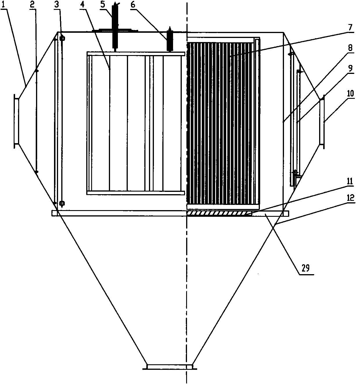
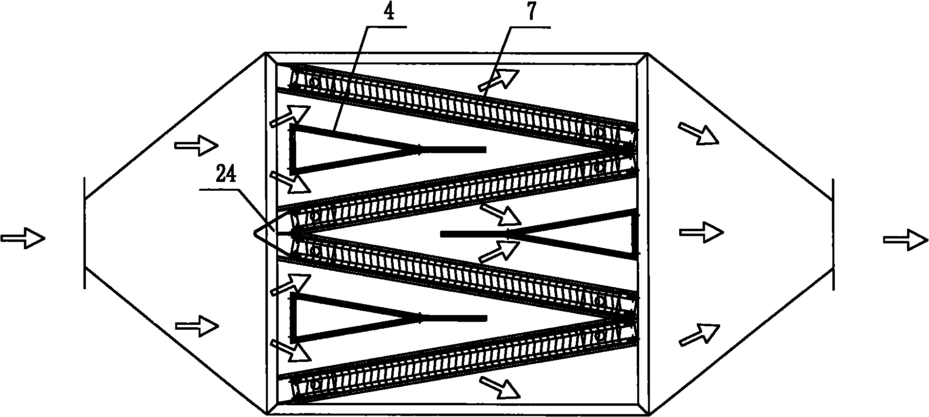
[0022] Such as figure 1 As shown, the differential electrostatic precipitator according to the present invention mainly includes an inlet head 1, an air flow uniform distribution device 2, an anode auxiliary discharge system 3, a cathode system 4, a high voltage introduction insulating hanger 5, an insulating hanger 6, and an anode system 7. Shell 8, outlet labyrinth plate 9, outlet head 10, diversion system 11, ash hopper 12, among which:

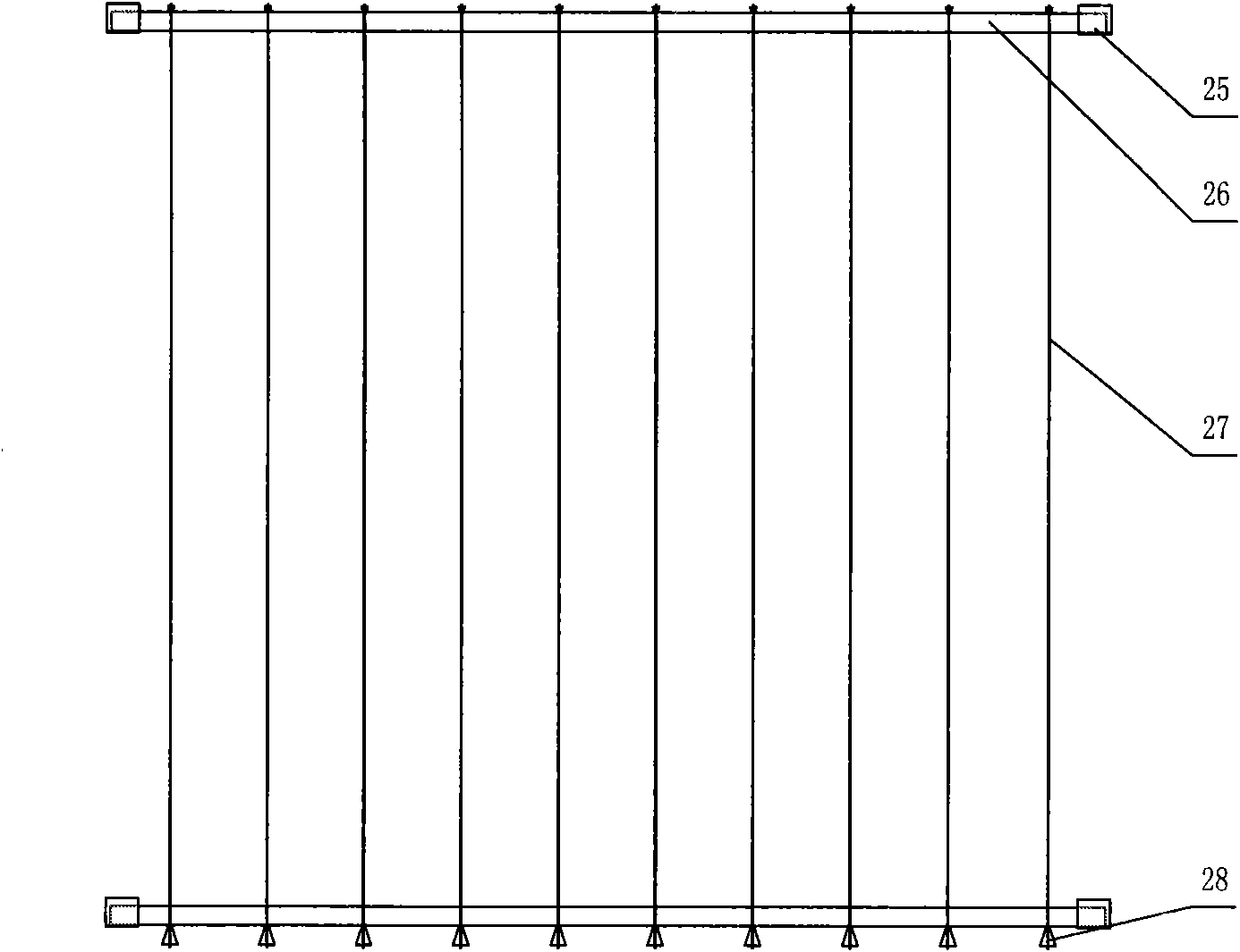
[0023] The ash hopper 12 is integrated with the shell 8 and is located below the shell 8. The inlet head 1 and the outlet head 10 are respectively located on both sides of the shell 8. An auxiliary discharge system 3 ( image 3 ), the auxiliary discharge system includes two parallel frames 25 connected to the housing 8, an auxiliary discharge limiting tube 26 is erected between the parallel frames 25, and a plurality of auxiliary discharge wires 27 are arranged in parallel under the auxiliary discharging limiting tube 26, and A weight 28...


PUM


Abstract

The invention discloses a differential electric precipitator, which comprises a shell, an ash bucket, an inlet seal head, an outlet seal head, a cathode system and an anode system. The ash bucket is connected with the shell through a bottom beam and is arranged below the shell, the inlet seal head and the outlet seal head are respectively arranged on the two sides of the shell, the cathode system and the anode system are arranged in the shell, and an auxiliary discharge system is arranged on the rear end of the inlet seal head, the anode system comprises a plurality of through type anodes for fume to transversely penetrate through, each two through type anodes form a wedge shape from the inlet seal head side to the outlet seal head side, and the contacts of the through type anodes on the inlet seal head side are connected via a V-shaped deflector; and the cathode system consists of a plurality of small cathode frameworks, and each small framework is independently hanged in an insulating way and is arranged in a triangular space between the anode system and the auxiliary anode discharge system. The invention reduces the average distance between dust and the anode plate, avoids the anti-corona scene caused by the dust with high specific resistance, improves the ash cleaning effect, and prevents the secondary dust.

Description

technical field [0001] The invention relates to a dust control device, in particular to a differential electrostatic precipitator. Background technique [0002] With the continuous improvement of the degree of industrialization, the environmental pollution in the world is increasing day by day, and the improvement and protection of the environment have been paid more and more attention by people from all walks of life. To this end, China has continuously improved the emission standards of smoke and dust, from the initial 80mg / m 3 Gradually drop to 30-50mg / m 3 Even below, dust removal systems in various industries such as electric power, building materials, steel, and non-ferrous smelting are facing an unprecedented test, and the following situations have occurred: [0003] 1. Electric power industry: As coal resources decrease year by year, the quality of coal used in boilers also decreases, resulting in a large increase in smoke and dust content, and the specific resistan...

Claims


Application Information

Patent Timeline
IPC IPC(8): B03C3/04B03C3/34B03C3/40
Inventor 雷统淼江保祥冯浩李焕勇
Owner 江苏力洁达环保设备工程有限公司
Why Eureka
Try Eureka