Device for measuring brightness

A luminance measurement, one-way technology, applied in the field of measuring optical radiation measurement devices, can solve the problems of impossibility, influence on luminance measurement, inconvenient operation, etc., and achieve the effects of high repeatability, convenient operation, and high measurement accuracy

Active Publication Date: 2010-08-25
HANGZHOU EVERFINE PHOTO E INFO
View PDF2 Cites 9 Cited by
  • Summary
  • Abstract
  • Description
  • Claims
  • Application Information

AI Technical Summary

Problems solved by technology

These existing aim-point luminance meters have the following common defects: in the measurement, the human eye observes the surrounding environment through the eyepiece and adjusts the position of the luminance meter to aim at the point to be measured
On the one hand, this measurement method is inconvenient to operate. When measuring, the human eye needs to constantly switch between the eyepiece and the measurement data display screen; on the other hand, the judgment and selection of the measured point is completely dependent on the human eye. Realization, it is easy to introduce human factors, thus affecting the measurement of brightness
It is impossible for the existing point-and-point luminance meter to realize the memory of information such as the scene around the measurement point, and it is even more impossible to measure and record the brightness distribution value of the surrounding scene in the form of an image.

Method used


Image

  • Device for measuring brightness
  • Device for measuring brightness
  • Device for measuring brightness

Examples


Embodiment 1

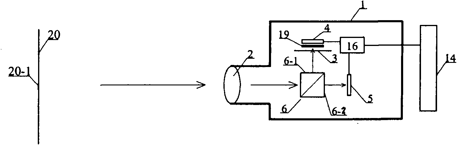
[0030] As shown in FIG. 1 , the luminance measuring device of the present invention includes a housing 1 , a lens 2 is arranged on the housing 1 , and the measured light beam of the measured object 20 enters the housing 1 from the lens 2 . The first beam splitter 6 is arranged behind the lens 2 and is a cubic prism 6 composed of two right-angle prisms and coated with a semi-transparent and semi-reflective film on the surface where the two prisms are bonded. The cubic prism 6 has two light-emitting The first light outlet is 6-1, and the second light outlet is 6-2. The light emitted from the first light outlet 6-1 passes through the aperture diaphragm 3 and is received by the first photodetector 4. The first photodetector 4 is a single-channel silicon photocell. A color filter 2 19 is also provided at the front to match the relative spectral sensitivity of the first photodetector 4 to the V(λ) curve. The light emitted from the second light outlet 6-2 is received by the second p...

Embodiment 2

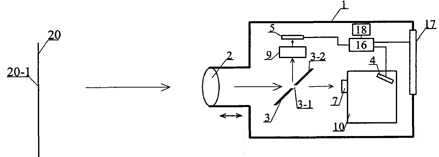
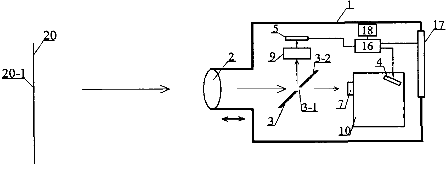
[0032] As shown in FIG. 2 , the embodiment includes a housing 1, and the measured light beam of the measured object 20 enters the housing 1 from the lens 2, and a mirror-type small hole field stop 3 is arranged on the optical path behind the lens 2. The aperture field stop 3 is a reflector with a small hole 3-1, and the small hole 3-1 and the aiming point 20-1 on the measured target 20 are in a conjugate relationship of optical imaging. The measured light beam from the aiming point 20-1 passes through the lens and passes through the small hole-3-1 and is received by the light collecting device 7, and the light received by the light collecting device 7 is coupled to an optical dispersion device 10 (this embodiment). Using a fast spectroradiometer), the photodetection element of the fast spectroradiometer is a first photodetector 4, and the first photodetector 4 is a one-dimensional CCD. The measured light beams of other measured objects except the aiming point are reflected by ...

Embodiment 3

[0035] As shown in FIG. 3 , the structure of this embodiment is similar to that of Embodiment 2, but a second beam splitter 11 is arranged between the aperture diaphragm 3 and the light collecting device 7 , and the second beam splitter is a half Transflective cubic prism 11, which receives the light beam passing through the small hole 3-1 of the small hole field diaphragm 3, that is, the light beam from the aiming point 20-1, and divides the light beam into two beams, a part of which is still collected by the light collecting device 7 receives, enters the optical dispersion device 10 (this embodiment uses a fast spectroradiometer), the other part is provided with a third photodetector 12 with a color filter 13 in front, and the third photodetector 12 is a single-channel silicon photocell, The color filter 13 makes the relative spectral sensitivity S(λ) of the silicon photovoltaic cell to incident light rel It matches the V(λ) curve. At the same time, a color filter 8 is also...


PUM


Abstract

The invention discloses a device for measuring brightness, which comprises a shell, wherein a lens is arranged at an incident port of the shell. Light from the lens is divided into two beams, wherein one beam is received by a first photoelectric detector through an aperture field diaphragm, while the other beam is received by a second photoelectric detector. The first photoelectric detector measures the brightness and spectrum parameters of an aiming point, and the second photoelectric detector can simultaneously display and record illumination information of peripheral environment of the aiming point, and measure image brightness. The device for measuring the brightness has high measurement accuracy, can simultaneously provide brightness values of photopic vision, scotopic vision and mesopic vision, and has the characteristics of complete measurement functions, convenient operation and high repeatability.

Description

【Technical field】 [0001] The invention relates to a measuring device for measuring light radiation, in particular to a device for measuring brightness. 【Background technique】 [0002] Brightness or radiance refers to the light intensity (radiant intensity) of a light source per unit area in a certain direction, and the unit is cd / m 2 (W / m 2 / sr), which directly reflects the human eye's perception of light, and has a very wide range of applications in the fields of flat panel display, lighting engineering and light source design. Therefore, the convenient and accurate measurement of brightness (radiance) is very important. The instrument for measuring brightness is a brightness meter. The current brightness meters can be divided into shading cylinder brightness meters, aiming point brightness meters and image brightness meters. The shading cylinder luminance meter uses the contact method to measure the luminance, the measured area is large, the measurement is limited and t...

Claims


Application Information

Patent Timeline
Patent Type & Authority Applications(China)
IPC IPC(8): G01J1/42G01J1/04G01J3/28
Inventor 潘建根
Owner HANGZHOU EVERFINE PHOTO E INFO
Why Eureka
Try Eureka