Production process and production equipment of sludge and garbage carbonized slurry fuel

A waste carbonization pulp and production process technology, applied in the direction of liquid carbon-containing fuel, fuel, petroleum industry, etc., can solve the problems of complex process technology, difficult promotion and use, high production cost, etc., achieve short process flow, low power consumption per ton, The effect of high equipment reliability

Inactive Publication Date: 2012-11-07
汪建林
View PDF1 Cites 0 Cited by
  • Summary
  • Abstract
  • Description
  • Claims
  • Application Information

AI Technical Summary

Problems solved by technology

Among them, Japan usually adopts a high-temperature and atmospheric-pressure carbonization process, which is complicated in technology, high in energy consumption, and high in production costs, so it is not easy to promote and use.

Method used


Image

  • Production process and production equipment of sludge and garbage carbonized slurry fuel
  • Production process and production equipment of sludge and garbage carbonized slurry fuel

Examples


Embodiment 1

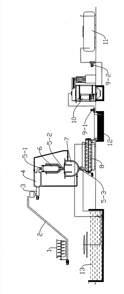
[0020] In this embodiment, the production equipment of the present invention includes a material agitator 1, a horizontally arranged high-pressure feed pump 3 and a jacketed preheating chamber 4, and a vertically arranged carbonization chamber connected to the outlet of the preheating chamber 4. The reaction kettle 6 is provided with a first electric control valve 5-1 at the outlet of the preheating chamber 4, and a decompression switch with an inner and outer jacket is connected to the carbonization reaction kettle 6 through the second electric control valve 5-2. Heater 7, the decompression heat exchanger 7 is connected to a spiral cooling device 8 through the third electronically controlled valve 5-3, and the spiral cooling device 8 is provided with a delivery pipeline leading to a mixing tank 12; the mixing tank passes through the pipeline The first slurry pump 9-1 is connected with the vertical planetary mill 10, and the vertical planetary mill 10 is connected with the seco...

Embodiment 2

[0026] In this embodiment, in order to further improve the production efficiency of the present invention, when setting up the production equipment system, a larger-volume decompression heat exchanger can be set up, and then two sets of separate preheating chambers and carbonization kettles can be set up. A separate set of preheating chambers and carbonization kettles are connected to this decompression heat exchanger. In this way, during production, the two sets of preheating bins and carbonization kettles can alternately feed and discharge materials, making the process smooth, making full use of the space of the equipment, and improving production efficiency.

[0027] In this embodiment, in the process steps of mixing, pressurizing, and preheating: the mixed material is heated to 200 degrees Celsius by the high-temperature steam in the bulkhead jacket in the preheating chamber.

[0028] In the high-pressure carbonization step: the carbonization kettle is preheated to 315 deg...


PUM


Abstract

The invention relates to a production process and production equipment of sludge and garbage carbonized slurry fuel, belonging to the technical field of new energy, and comprising the following processing steps: heating sludge and household garbage particles to 150-200 DEG C; cracking the mixed materials at 300-350 DEG C and under the pressure of 10MPa into carbonized slurry, i.e. completing the carbonizing procedure; pouring the carbonized slurry into a depressurizing heat exchanger for depressurizing and heat exchanging; cooling by utilizing a screw cooler; and pumping the cooled carbonizedslurry into a vertical planetary mill to carry out ultrafine grinding to achieve 400 meshes / D95, and then leading the slurry to enter into a slurry storing tank. The production equipment of the invention comprises a material stirrer, a preheating bin, a carburizing reaction kettle, the depressurizing heat exchanger, the screw cooler with heat radiating fins, a slurry mixing pool, the vertical planetary mill and the slurry storing tank, wherein the vertical planetary mill is connected with the slurry storing tank. The invention uses the sludge and the household garbage as raw materials to produce the carbonized slurry fuel, and has short process flow, high equipment reliability and small production energy consumption.

Description

Technical field: [0001] The invention relates to a sludge and garbage carbonized pulp fuel production process and production equipment, belonging to the technical field of new energy sources. Background technique: [0002] At present, 90% of the sludge is landfilled or discarded without any treatment, causing serious environmental and groundwater pollution. Effective treatment measures are urgently needed to change the status quo. The sludge transported from the sewage plant generally contains 80% water and 20% organic matter. Therefore, the traditional sludge drying method needs to evaporate a large amount of water, and the energy consumption is very high. The United States, Japan and other countries have successively developed the process of carbonizing sludge. The main process route is: sludge is carbonized, then dehydrated (sewage is retreated), then dried, pressed into carbonized blocks, and used as a low-calorie fuel and coal Carry out mixed burning. Among them, Japa...

Claims


Application Information

Patent Timeline
Patent Type & Authority Patents(China)
IPC IPC(8): C10L1/32C10B53/00C10B57/08
Inventor 汪建林
Owner 汪建林
Why Eureka
Try Eureka