Straw fuel flying furnace

A fly-burning furnace and fuel technology, applied in the field of heating equipment, can solve the problems of restriction implementation and cost increase, and achieve the effects of not easy to pile up, save coal, and make full use of it

Active Publication Date: 2010-09-01
张建臣
View PDF10 Cites 13 Cited by
  • Summary
  • Abstract
  • Description
  • Claims
  • Application Information

AI Technical Summary

Problems solved by technology

However, the implementation of this technology has been limited due to increased costs

Method used


Image

  • Straw fuel flying furnace
  • Straw fuel flying furnace
  • Straw fuel flying furnace

Examples


Embodiment Construction

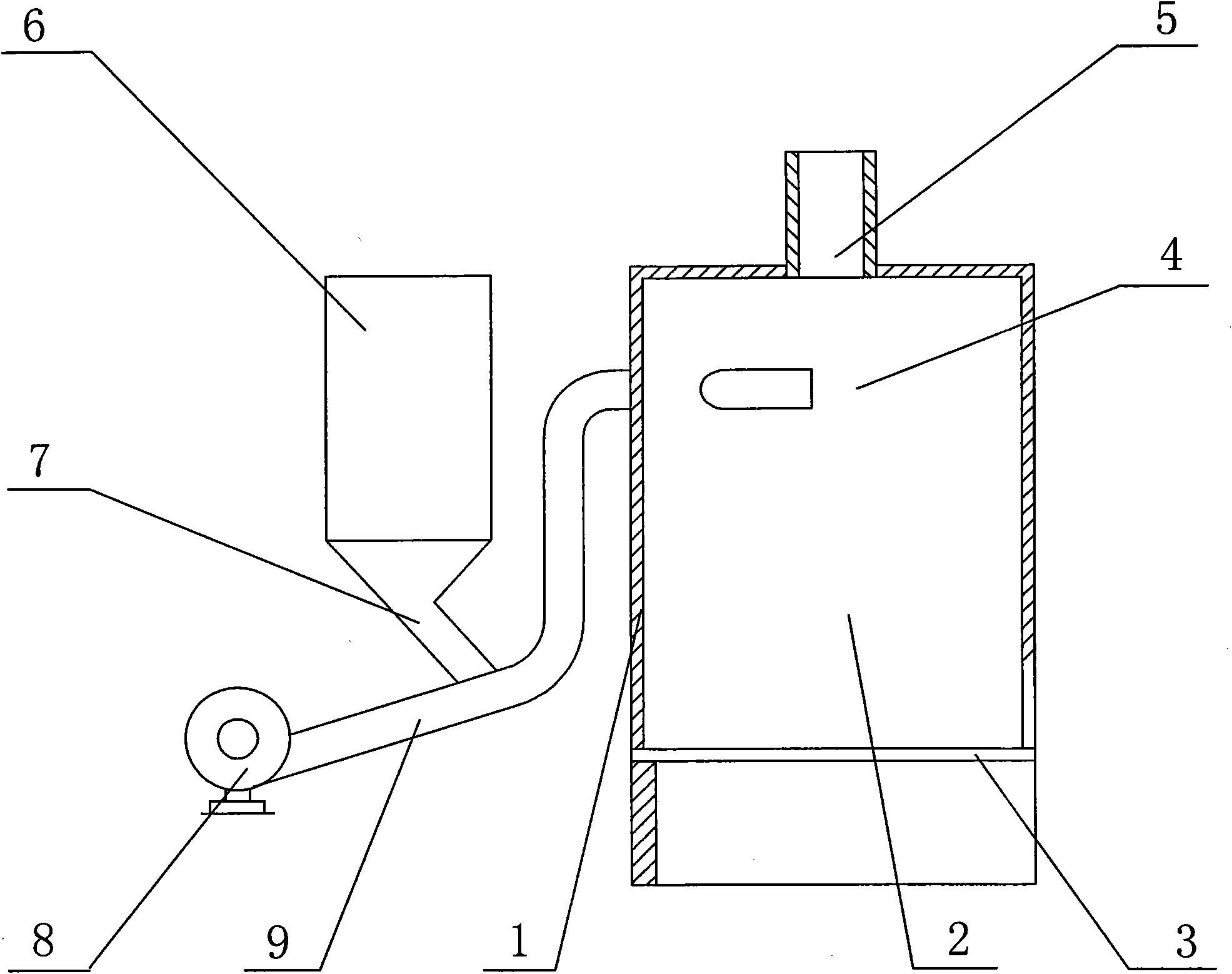
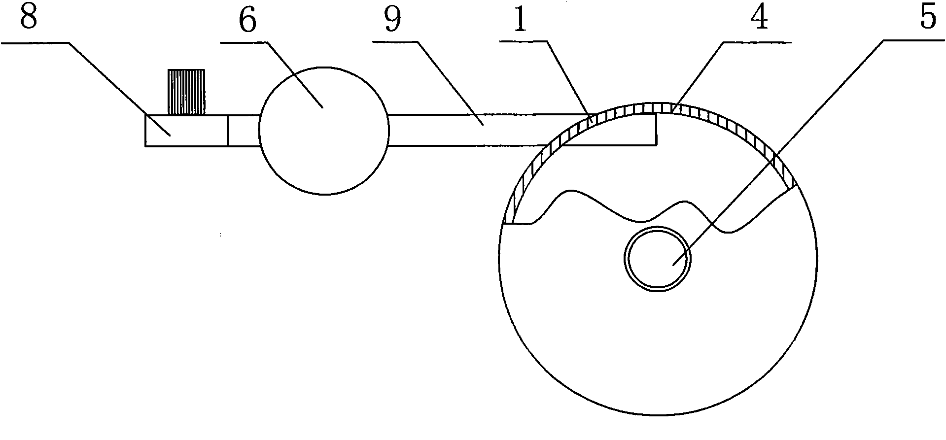
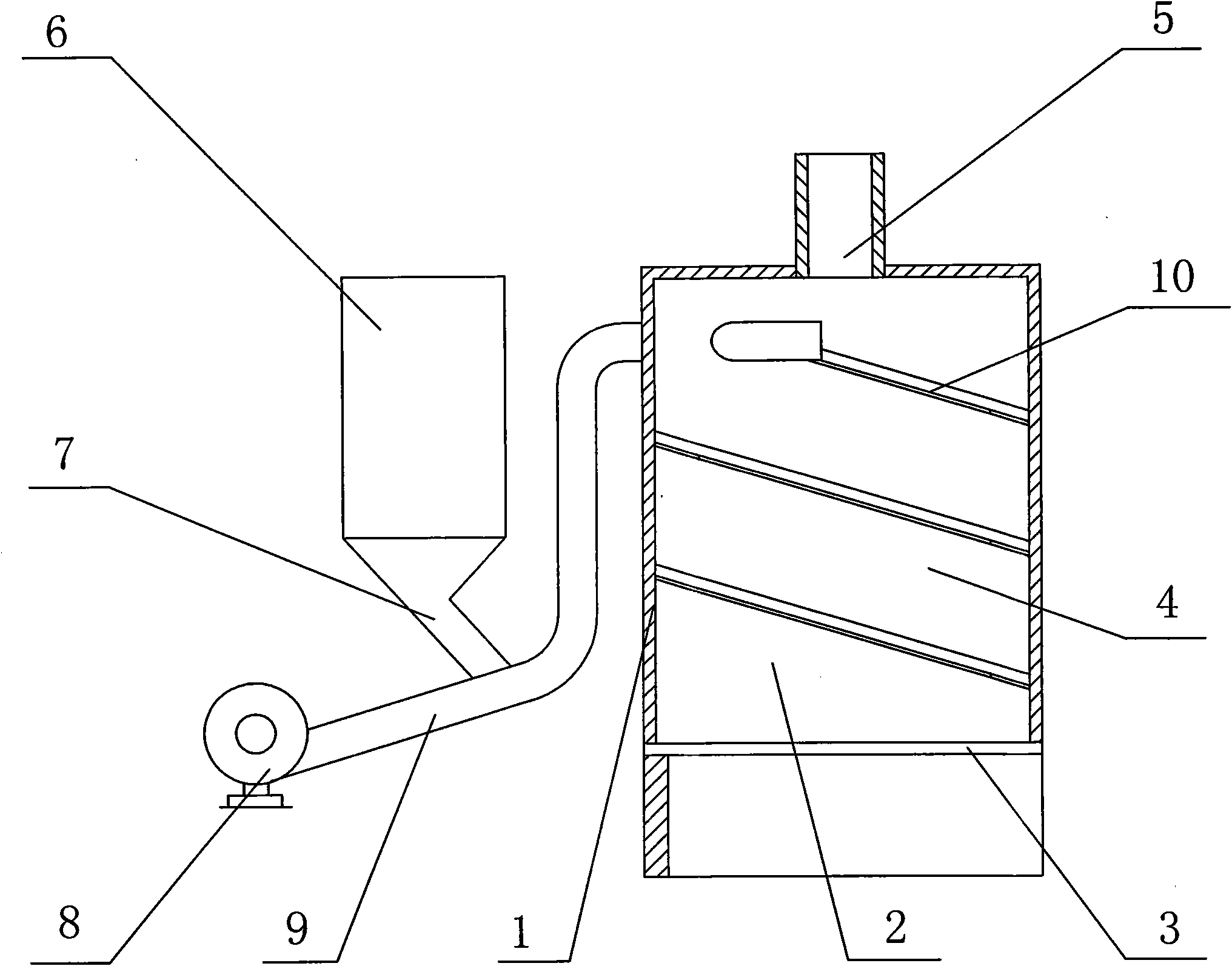
[0039] The first example: as figure 1 , 2 As shown, this straw burning furnace is composed of a furnace body 1, a furnace hearth 2, a grate 3, a smoke exhaust pipe 5, and the like. Outside the furnace body 3, there is a fuel hopper 6, and below the fuel hopper 6 there is a downwardly extending drop pipe 7. A fan 8 is provided below the fuel hopper 6 , and the end of the air supply pipe 9 of the fan 8 enters the furnace 2 . The blanking pipe 7 under the fuel hopper 6 communicates with the air supply pipe 9 . The air supply pipe 9 of the fan 8 contacts a section of the cyclone guide curved surface 4 after entering the furnace 2 . There are various forms of the cyclone guide curved surface 4. In this example, the inner wall of the circular furnace body 1 is borrowed. In order to use this inner wall, the outer end of the air supply pipe 9 is at the upper part of the furnace chamber 2, along the tangent of the arc surface of the inner wall of the furnace chamber. Directions int...


PUM


Abstract

The invention relates to heat supply equipment, in particular to a straw fuel flying furnace which comprises a furnace body (1), a hearth (2), a fire grate (3) and a smoke exhaust pipe (5), wherein the furnace body (1) is externally connected with a fan (8), and an air supply pipe (9) of the fan (8) enters the hearth (2) from one side of the furnace body. The straw fuel flying furnace is characterized in that a fuel hopper (6) is arranged outside the furnace body (1), a blanking pipe (7) under the fuel hopper (6) is communicated with the air supply pipe (9) of the fan (8); and one end of the air supply pipe (9) entering the hearth (2) is provided with a cyclone guide curved surface (4). Fuel is combusted in rotatably flying after entering the hearth following wind, is not easy to accumulate, and is fully combusted. The fan blows the fuel by using hot air in the hearth to ensure that straws are heated in advance to be ignited. The furnace body and a flue are both provided with residual head recovery devices, thereby closing various channels of heat loss and remarkably improving the heat efficiency. The invention is suitable for being used as various heat exchange devices of a hot air furnace, a hot water furnace, an oil furnace and the like, replaces coal furnaces to carry out various heat supply operations, and has important implications on saving coal, protecting environment, fully utilizing crop plants, improving the straw value, and increasing the income of farmers.

Description

technical field [0001] The invention relates to a heating device, namely a straw fuel flying stove. Background technique [0002] At present, most of the heating equipment uses coal as fuel. With the development of the economy, coal resources are becoming increasingly scarce, and the pollution of coal-fired emissions to the environment is also of great concern. Therefore, seeking other alternative fuels to save coal and protect the environment has become a top priority. On the other hand, with the popularization and application of crop density planting technology, the output of crop straw has doubled. In addition, in recent years, a large number of household appliances have entered villages and towns, and electricity, biogas and gas have become popular rapidly. The crop straw, which was once the main living fuel in rural areas, has been replaced, resulting in a large surplus of straw that is difficult to handle. Experiments have shown that the calorific value of crop straw...

Claims


Application Information

Patent Timeline
Patent Type & Authority Applications(China)
IPC IPC(8): F23B40/00F23L15/00
CPCY02E20/34
Inventor 张建臣
Owner 张建臣
Why Eureka
Try Eureka