Parallel-type permanent magnet direct-drive wind power converter in wind driven generation system and control method thereof

A technology of wind power generation system and wind power converter, which is applied in the direction of wind power generation, AC power input conversion to AC power output, electrical components, etc., can solve the problems of complex control methods and system volume increase, and achieve broad application range, The effect of reduced volume and simple control method

Active Publication Date: 2010-09-08
HARBIN INST OF TECH
View PDF1 Cites 39 Cited by
  • Summary
  • Abstract
  • Description
  • Claims
  • Application Information

AI Technical Summary

Problems solved by technology

[0006] The purpose of the present invention is to provide a parallel pe

Method used


Image

  • Parallel-type permanent magnet direct-drive wind power converter in wind driven generation system and control method thereof
  • Parallel-type permanent magnet direct-drive wind power converter in wind driven generation system and control method thereof
  • Parallel-type permanent magnet direct-drive wind power converter in wind driven generation system and control method thereof

Examples


specific Embodiment approach 1

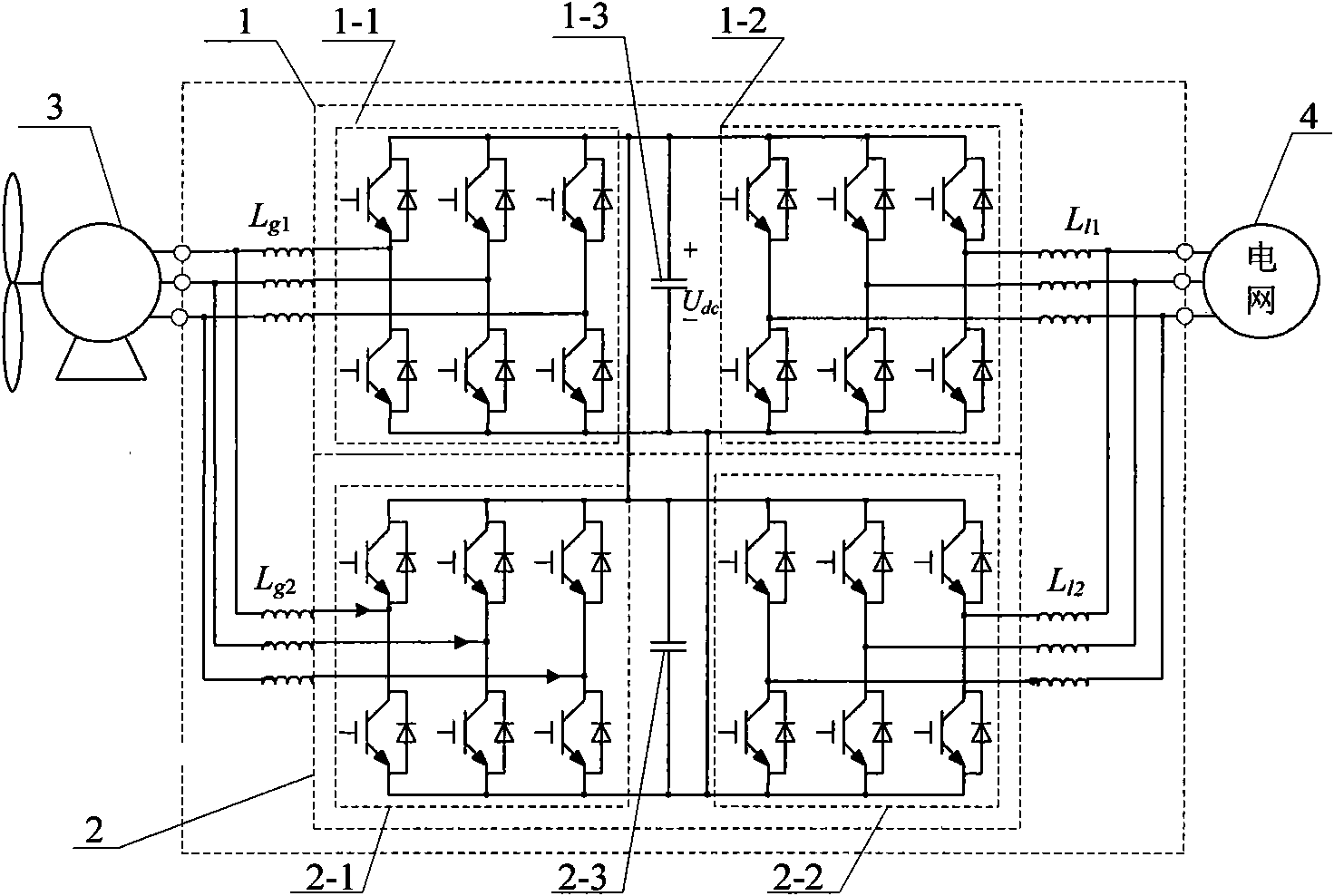
[0035] Specific implementation mode one: the following combination figure 1 Describe this embodiment, this embodiment includes a first back-to-back PWM converter module 1 and a second back-to-back PWM converter module 2, which also includes a first input-side three-phase reactor L g1 , the first output side three-phase reactor L l1 , the second input side three-phase reactor L g2 , the second output side three-phase reactor L l2 ,

[0036] The first back-to-back PWM converter module 1 and the second back-to-back PWM converter module 2 are connected in parallel on the DC bus, and the machine-side input end of the first back-to-back PWM converter module 1 and the three-phase wind power of the converter A three-phase reactor L on the first input side is connected in series between the power generation input terminals g1 , a second input-side three-phase reactor L is connected in series between the machine-side input end of the second back-to-back PWM converter module 2 and th...

specific Embodiment approach 2

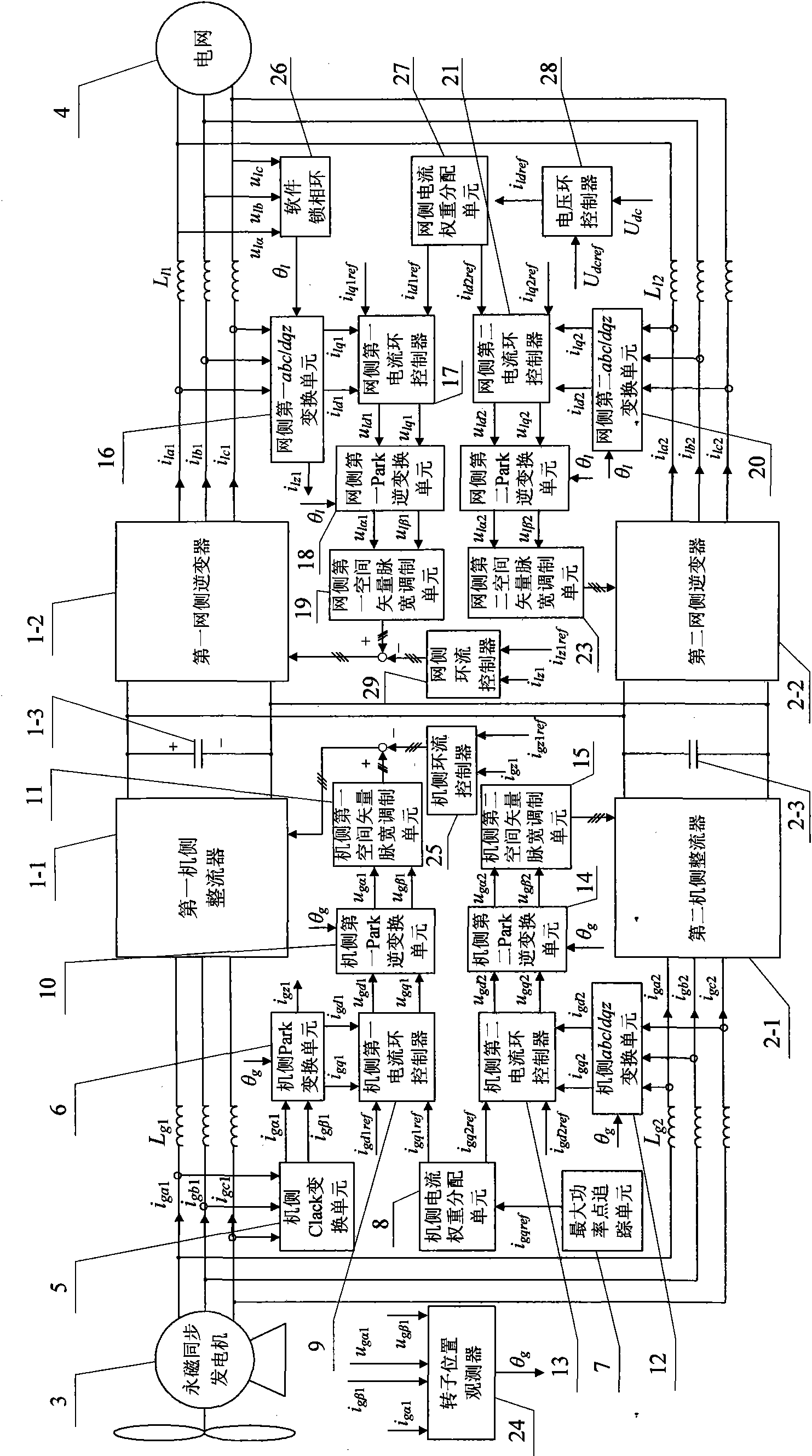
[0041] Specific implementation mode two: the following combination Figure 2 to Figure 4 This embodiment is described. This embodiment is based on the control method of the parallel permanent magnet direct-drive wind power converter in the wind power generation system described in Embodiment 1. The control method is realized based on the following wind power generation system. The wind power generation system The three-phase wind power generation input terminal of the converter described in is connected with the three-phase power generation signal output terminal of the permanent magnet synchronous generator 3, and the three-phase grid signal output terminal of the converter is connected with the three-phase power signal output terminal of the grid 4 The input terminal is connected;

[0042] The control method of the parallel permanent magnet direct drive wind power converter in the wind power generation system is:

[0043] Collect the first input side three-phase reactor L ...


PUM


Abstract

The invention relates to a parallel-type permanent magnet direct-drive wind power converter in a wind driven generation system and a control method thereof, belonging to the technical field of power electronics, which solve the problems of increased system volume and complex control method in a traditional parallel converter when the circular flow problem is solved. The parallel-type permanent magnet direct-drive wind power converter consists of two sets of back-to-back PWM (Pulse-Width Modulation) converter module, two input side three-phase reactors and two output side three-phase reactors, wherein each set of back-to-back PWM converter module consists of a rectifier, an inverter and a capacitor. In the control method, a machine side circular flow controller is adopted at a machine side and the output of the machine side circular flow controller is compensated to the initial three-phase duty ratio of a first machine side rectifier; a net side circular flow controller is adopted at a net side and the output of the net side circular flow controller is compensated to the initial three-phase duty ratio of a first net side inverter, thereby respectively adjusting three-phase duty ratio signals of the back-to-back PWM converter modules and achieving the purpose of inhibiting the circular flow. The invention is used for conveying energy of a higher-power generator to power grid.

Description

technical field [0001] The invention relates to a parallel permanent magnet direct drive wind power converter in a wind power generation system and a control method thereof, belonging to the technical field of power electronics. Background technique [0002] With the increasing shortage of energy, the prominent environmental problems and the advancement of power electronic technology and devices, wind power generation has been continuously developed. Among the various schemes of wind power generation, the permanent magnet direct drive wind power generation method has increasingly become a research and application hotspot due to its superior performance. It saves the gearbox and slip ring, reduces the system noise, greatly reduces the volume of the system, reduces the cost, improves the reliability of the system, and greatly reduces the maintenance cost; due to the use of permanent magnet excitation, there is no rotor Copper loss, and improved power generation efficiency. T...

Claims


Application Information

Patent Timeline
IPC IPC(8): H02M5/458H02J3/38H02J3/01
CPCY02E10/763Y02E10/76Y02E40/40
Inventor 徐殿国李瑞徐壮李广军
Owner HARBIN INST OF TECH
Why Eureka
Try Eureka