Crystal annealing device in growth furnace

An annealing device and growth furnace technology, applied in crystal growth, post-processing details, post-processing, etc., can solve problems such as long annealing time, high annealing temperature, release and resolution of crystal internal stress, etc., and achieve low production cost , reduce internal stress, reduce the effect of internal defects

Inactive Publication Date: 2010-09-15
FUJIAN INST OF RES ON THE STRUCTURE OF MATTER CHINESE ACAD OF SCI
View PDF2 Cites 4 Cited by
  • Summary
  • Abstract
  • Description
  • Claims
  • Application Information

AI Technical Summary

Problems solved by technology

After the crystal growth is completed, follow-up annealing is carried out outside the furnace. Since the annealing temperature is difficult to be high (generally below 1300 degrees), the internal stress of the crystal and the defects caused by thermal stress cannot be completely released and released in the follow-up outside the furnace annealing. solve
At the same time, the additional out-of-furnace annealing also requires a longer annealing time

Method used


Image

  • Crystal annealing device in growth furnace
  • Crystal annealing device in growth furnace

Examples


Embodiment 1

[0012] Example 1: Laser crystal growth of neodymium-doped yttrium aluminum garnet

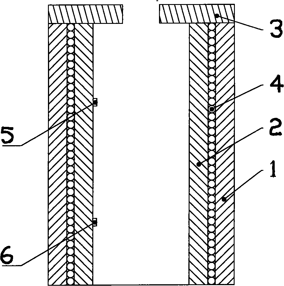
[0013] It adopts domestic DJL-600 type single crystal growth furnace, 50KW thyristor intermediate frequency induction power heating, double platinum rhodium (Pt / Rh30-Pt / Rh10) thermocouple, British Euro 818 temperature regulator.

[0014] Technical parameters used for crystal growth: 1) Seed crystal orientation: a-axis; 2) Growth atmosphere and pressure: N 2 , 50KPa; 3) Pulling rate: 0.5~1.0m / h; 4) Rotation rate: 10~15rpm; 5) The inner cavity height of the rear heater: 160~200mm; 6) Annealing rate: 10~15K / h( >1200°c), 30~50K / h (<1200°C).

[0015] Use Grade shallow iridium crucible, and made of Al 2 O 3 Tube, Pt radiant tube, Pt baffle plate and other components of the after-heating chamber. By adjusting the relative position of the crucible and the induction coil and the heating wire power in the upper heat preservation cover, the gas-liquid temperature difference on both sides of the melt surface ca...

Embodiment 2

[0016] Example 2: Scintillation crystal growth of cerium-doped yttrium lutetium silicate

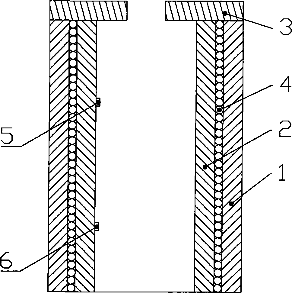
[0017] It adopts domestic DJL-600 type single crystal growth furnace, 50KW thyristor intermediate frequency induction power heating, double platinum rhodium (Pt / Rh30-Pt / Rh10) thermocouple, British Euro 818 temperature regulator.

[0018] Technical parameters used for crystal growth: 1) Seed crystal orientation: a-axis; 2) Growth atmosphere and pressure: N 2 , 50KPa; 3) Pulling rate: 0.5~1.0m / h; 4) Rotation rate: 10~15rpm; 5) The inner cavity height of the rear heater: 160~200mm; 6) Annealing rate: 10~15K / h( >1200°c), 30~50K / h (<1200°C).

[0019] Use Grade shallow iridium crucible, and made of Al 2 O 3 Tube, Pt radiant tube, Pt baffle plate and other components of the after-heating chamber. By adjusting the relative position of the crucible and the induction coil and the heating wire power in the upper heat preservation cover, the gas-liquid temperature difference on both sides of the melt sur...


PUM


Abstract

The invention relates to a crystal annealing device in a growth furnace. The heating power of a heat chromium-aluminum high-temperature heating wire which is wound on an inner layer and an outer layer of heat insulating covers is adjusted by measuring the temperatures of two double platinum-rhodium thermocouples, and a heating source is provided; and an annealing space with the relatively small temperature gradient is formed in the upper heat insulating cover, and then the temperature gradients on a head part and a tail part of the crystal are smaller, so that an inner thermal stress of the crystal can be reduced. By using the method, the high-temperature crystal with the low internal stress can be grown, the crystal can be directly oriented and cut after annealing of crystal growth and crystal elements with all kinds of specifications are prepared without long-time annealing outside the furnace, so that the internal stress of the crystal is greatly reduced, the internal defects are reduced, the efficiency is greatly improved, and the device has simple structure and low manufacturing cost and is suitable for batch production.

Description

Technical field [0001] The invention belongs to the technical field of artificial crystal preparation, and particularly relates to the structure and principle of a crystal annealing device in a growth furnace. Background technique [0002] Growing crystals from pure melts is one of the most common crystal growth methods. The biggest advantage of pure melt crystal growth is a much higher growth rate than other methods. The second is that the grown crystals are relatively less impurity encapsulated, but the crystals grown by this method have higher thermal stress, dislocations and grain boundaries. More serious. [0003] High melting point functional crystals can be grown by pure melt pulling method, such as laser crystal yttrium iron garnet and scintillation crystal cerium-doped yttrium lutetium silicate, etc. The growth temperature of these crystals is generally around 2000 ℃. After the crystal growth is completed, the heating power needs to be gradually reduced and slowly drop t...

Claims


Application Information

Patent Timeline
Patent Type & Authority Applications(China)
IPC IPC(8): C30B33/02
Inventor 吴少凡林文雄
Owner FUJIAN INST OF RES ON THE STRUCTURE OF MATTER CHINESE ACAD OF SCI
Why Eureka
Try Eureka