Compound compensator for high pressure pipeline

A high-pressure pipeline and composite technology, which is applied to expansion compensation devices, pipe components, pipes/pipe joints/fittings, etc. for pipelines, and can solve problems such as weak anti-corrosion links, large gaps, and leakage.

Inactive Publication Date: 2010-09-15
陈墅庚
View PDF0 Cites 8 Cited by
  • Summary
  • Abstract
  • Description
  • Claims
  • Application Information

AI Technical Summary

Problems solved by technology

Among them: the cost of the spherical compensator is too high, while the performance of the domestically produced spherical compensator is average, and the pressure loss is relatively large; the corrugated compensator has too much stress in the pipeline in actual application, and there are always hidden safety hazards in the pipeline operation; and the use of the original Π-shaped compensator The investment and pressure loss of the natural compensation method are the same; the structure and sealing performance of the sleeve compensator are not good, the leakage phenomenon is serious, and the anti-corrosion link is also weak; the performance of the rotary compensator is better; it has a large amount of compensation, Flexible layout, especially in long-distance overhead pipelines, has obvious advantages; but there are also shortcomings: First, the gap between the joint part of the inner pipe and the reducing pipe is too large, and eddy currents will be generated at this part during the movement of the fluid medium. This increases the pressure loss of the fluid medium
Second, because the structure of the rotary compensator is a radial working principle, it must occupy a certain space when it is applied in the pipeline; and each set of compensator installation points must be equipped with a drain valve; this increases the cost and pressure loss of the pipeline network; Especially in buried pipelines, it cannot be widely used; especially spherical compensators, sleeve compensators, corrugated compensators, and rotary compensators all adopt a single sealing form. In terms of use: fluid medium and pressure bearing capacity, etc. subject to certain limitations

Method used


Image

  • Compound compensator for high pressure pipeline
  • Compound compensator for high pressure pipeline
  • Compound compensator for high pressure pipeline

Examples


Embodiment Construction

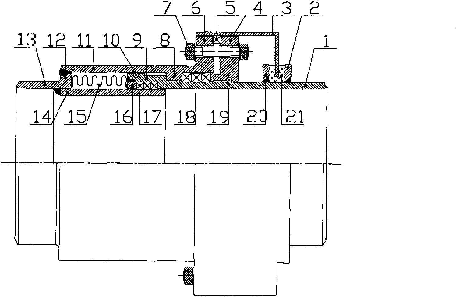
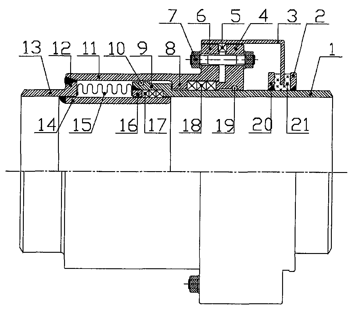
[0045] The technical solutions of the present invention are described in detail below in conjunction with the accompanying drawings.

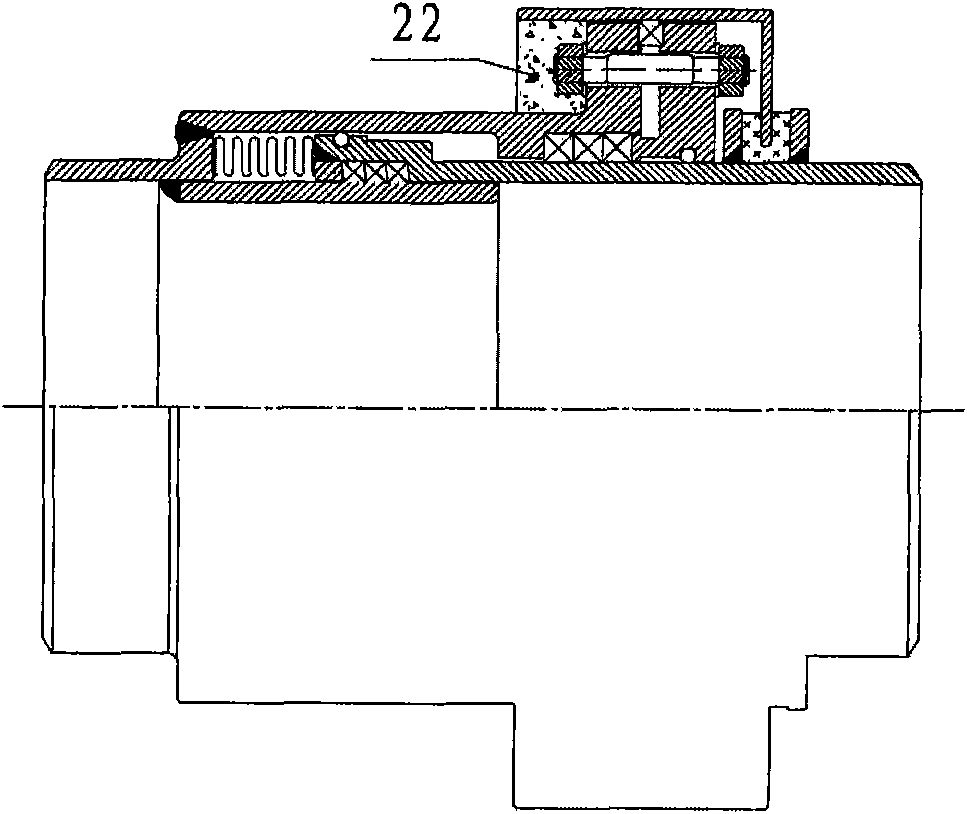
[0046] Such as figure 1 As shown in the figure, it can be seen from the figure that the composite compensator for high-pressure pipelines includes inner pipe 1, anti-corrosion pipe fixed pressure ring 2, anti-corrosion pipe 3, packing gland flange 4, sealing packing A5, outer casing flange 6 , Bolts and nuts 7, Outer sleeve inner bearing platform 8, Inner tube convex outer ring 9, Steel ball A10, Outer sleeve 11, Reducing pipe bearing platform 12, Reducing pipe 13, Drain pipe 14, Bellows 15, Binder head 16. Sealing packing B17, sealing packing C18, steel ball B19, anti-corrosion pipe fixed bottom beam 20 and heat insulating pad 21;

[0047]The sealing packing A5, sealing packing B17 and sealing packing C18 can be flexible graphite including metal reinforced flexible graphite, titanium fiber reinforced flexible graphite or flexible graphite add...


PUM


Abstract

The invention discloses a compound compensator for a high pressure pipeline, belonging to the technical field of the compensating equipment of the heat distribution pipeline. The compound compensator comprises an inner pipe, an anticorrosive pipe, a gland cover flange, a wear sleeve flange, a wear sleeve, a reduction adapter, a guide pipe, a corrugated pipe, a pressure head and the like, wherein the wear sleeve is ringed on one end of the inner pipe, the outer ring of the outer end of one side of the wear sleeve is provided with the wear sleeve flange, the end on other side of the wear sleeve is welded and fixed with a reduction adapter supporting platform integrated with the reduction adapter; the reduction adapter and the inner pipe are separately sleeved on the two ends of the guide pipe, one end of the guide pipe is fixedly connected with the reduction adapter, the corrugated pipe is arranged between the guide pipe and the wear sleeve, and the two ends are butted with the pressure head and the reduction adapter and are connected and fixed through welding. By adopting the structure, when the inner pipe is extruded and pushed by the axial heat expansive force, the axial displacement can be absorbed through the flexible deformation of the corrugated pipe; the coaxial, synchronous and integral movement of the anticorrosive pipe and the like along with the inner pipe can be performed along the axial direction, thus the compound compensator can be used as the buried pipeline or the overhead pipeline; in addition, the compound compensator has multifunctional characteristics of being used as the gas or liquid pipeline and also as the slurry pipeline.

Description

technical field [0001] The invention relates to a composite compensator for high-pressure pipelines, which belongs to the technical field of thermal pipeline compensation devices, and specifically belongs to the technical field of thermal pipeline compensation device structures used in industries such as petroleum, chemical industry, light industry, thermal power, and metallurgy. Background technique [0002] Common pipeline compensation methods in the prior art are as follows: 1. Traditional natural U-bend type, 2. Spherical compensator, 3. Sleeve compensator, 4. Corrugated compensator, 5. Rotary compensator. Among them: the cost of the spherical compensator is too high, while the performance of the domestically produced spherical compensator is average, and the pressure loss is relatively large; the corrugated compensator has too much stress in the pipeline in actual application, and there are always hidden safety hazards in the pipeline operation; and the use of the origin...

Claims


Application Information

Patent Timeline
Patent Type & Authority Applications(China)
IPC IPC(8): F16L51/02
Inventor 陈墅庚
Owner 陈墅庚
Why Eureka
Try Eureka