Small steel shot feeding circulator and numerical control metal surface treating machine using the same

A circulator and steel shot technology, applied in abrasive feeding devices, metal processing equipment, abrasives, etc., can solve the problems of complex structure and control, inability to transport the whole machine, difficult to change the working position, etc., and achieve production and transportation costs. The effect of lowering, simplification of structure and control, and improved maneuverability

Inactive Publication Date: 2010-09-22
天津新技术产业园区北洋世纪焊接技术有限公司
View PDF4 Cites 8 Cited by
  • Summary
  • Abstract
  • Description
  • Claims
  • Application Information

AI Technical Summary

Problems solved by technology

But this equipment has the following defects: (1) The three-dimensional operation of the shot blasting head needs to be completed through the control of three sets of mechanisms, that is: the hydraulic cylinder lifting mechanism directly pushes to complete the up and down operation, and the machine driven by the motor to push and pull the lead screw moves. The table completes the forward and backward movement facing the barrel, and the left and right movement along the axis of the barrel along with the entire walkable machine base. The structure and control are complex, especially the forward and backward movement is driven by the screw rod with small stroke, high friction, slow speed, and flexibility is not easy to guarantee.
(2) The steel shot circulation system consists of a feeding box that runs through the cylinder of the feeding cylinder, a steel shot lifting mechanism, a return box and a telescopic tube. The steel shot process is too long, the structure space is large, the system structure is complicated, the production cost is high, and the overall The control and movement of the machine is not flexible, and the safety and stability are poor. This structure also limits the expansion of the range of the shot blasting machine. At present, the up and down movement range of the shot blasting machine is only about 1 meter, which is only suitable for the surface treatment of large cylinders. For It is not applicable to the surface treatment of equipment manufacturing, ships, large petrochemical containers, large box bridges and other larger bodies including large plane structures
(3) The existing equipment is too large, the center of gravity is unstable, it cannot be rotated, and it is difficult to change the working position, so it is not suitable for production line operations, and can only handle workpieces on one side
(4) It is heavy and cannot be transported as a whole machine, especially inconvenient to assemble and disassemble, which increases the shipping cost

Method used


Image

  • Small steel shot feeding circulator and numerical control metal surface treating machine using the same
  • Small steel shot feeding circulator and numerical control metal surface treating machine using the same
  • Small steel shot feeding circulator and numerical control metal surface treating machine using the same

Examples


Embodiment 1

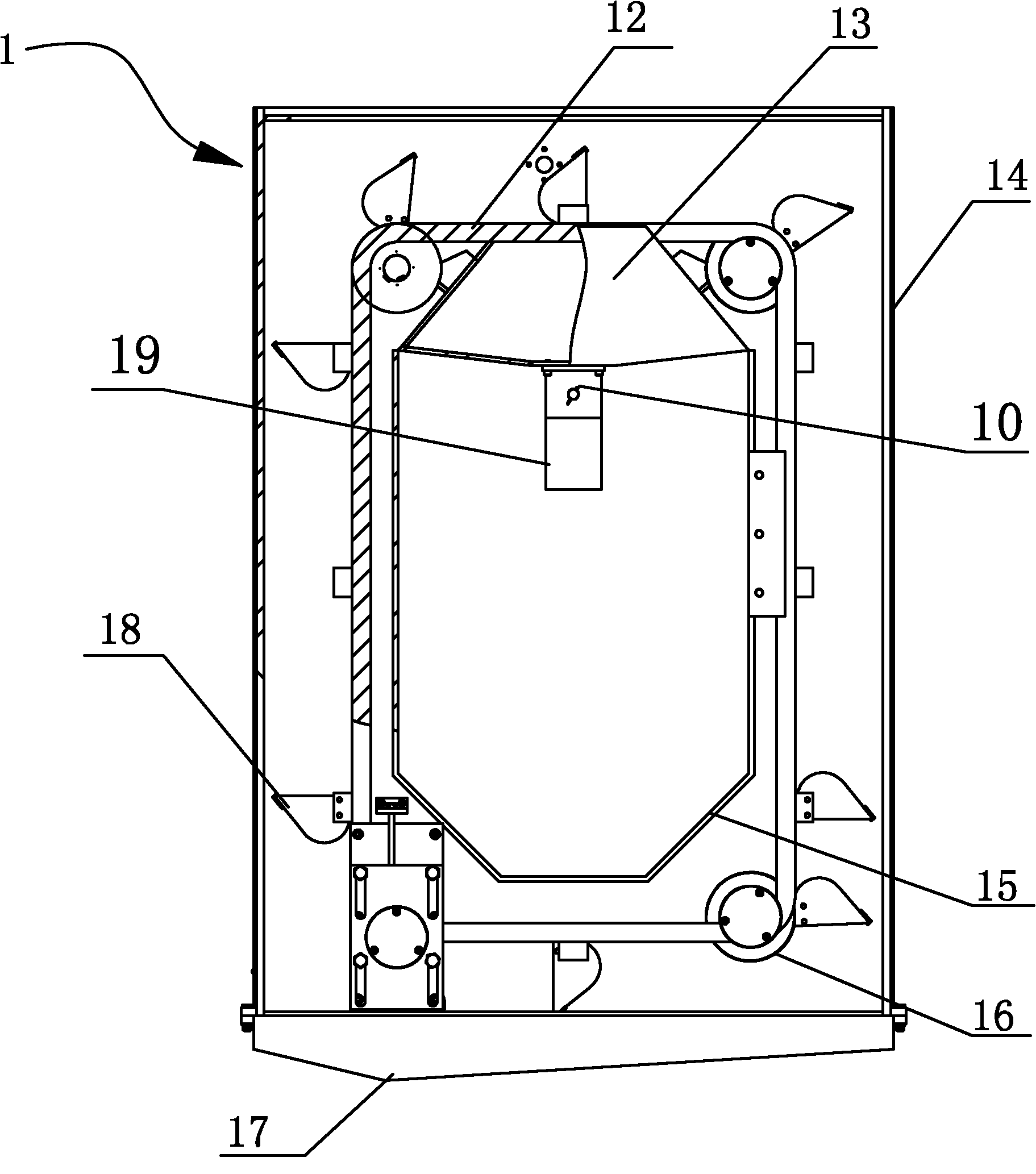
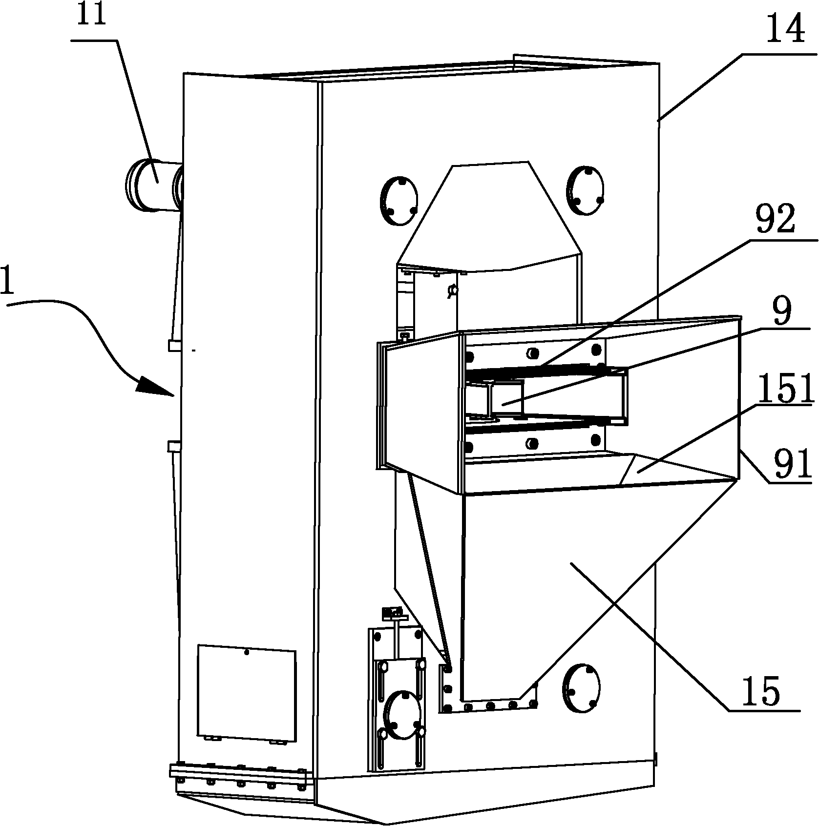
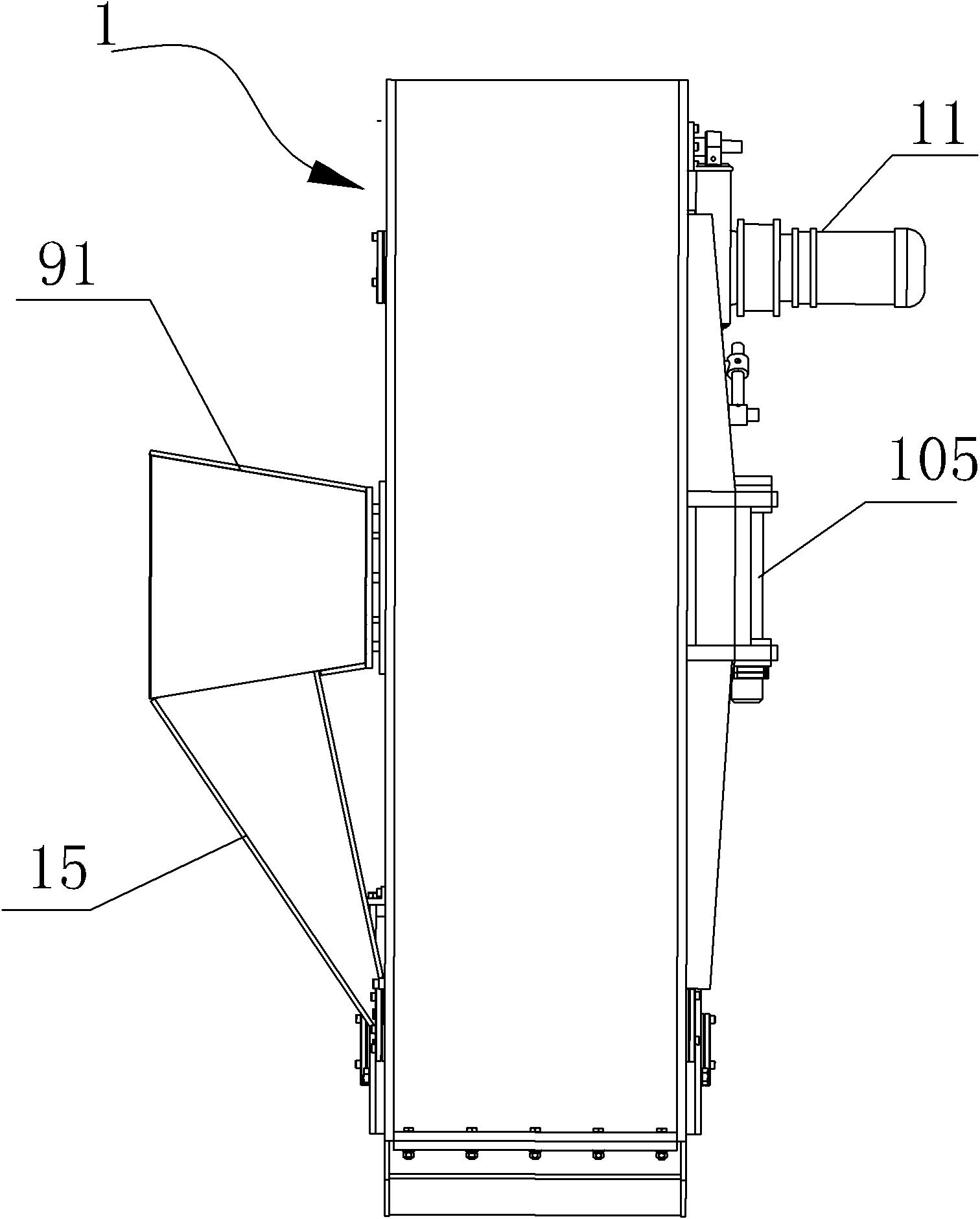
[0023] Figure 1 ~ Figure 4 Show a kind of small-sized steel shot feeding circulator and the overall structure after it is packed into the shot blasting device, the small-sized steel shot feeding circulator includes a feeding motor 11 for feeding the shot blasting device 9, and the feeding The double-layer sprocket 16 driven by the motor 11, the double-chain 12 meshed on the double-layer sprocket 16, and a plurality of feeding hoppers 18 connected between the double-chain are characterized in that a box 14 is provided, and the middle part of the box is shot blasting. The installation space of the device 9, the front wall of the box corresponding to the shot blasting device 9 is provided with a shot blasting window 92 and a sealing shield 91 extending out of the box, the above-mentioned feeding motor 11, multiple groups of double-layer sprockets 16, double chains 12 And a plurality of feeding hoppers 18 are arranged in the casing 14 around the blasting device 9; a feeding hoppe...

Embodiment 2

[0025] Figure 5 ~ Figure 7It shows a numerically controlled metal surface treatment machine, including a walking base 5, an operating room 7, a control box 6, a hydraulic station 4, a dust collector 3, a shot blaster 9, a mobile support arm for controlling the position of the shot blaster, and a feeding motor , the double-layer sprocket driven by the feeding motor, the double chain meshed with the double-layer sprocket and the steel shot feeding circulation system of multiple feeding hoppers connected between the double chains, the above-mentioned operation room 7, control box 6, hydraulic pressure The station 4, the dust collector 3 and the mobile support arm are set on the walking base 5; the operation panel 71 of the above-mentioned operation room 7 is electrically connected to the dust collector 3, the steel shot feeding cycle system, the shot blasting machine 9 and the walking base 5 through the control box 6. Connected, and hydraulically connected with the mobile suppor...


PUM


Abstract

The invention relates to a small steel shot feeding circulator, which comprises a feeding motor, a dual-layer sprocket, double chains and a plurality of feeding funnels, and is characterized in that a box body is arranged, an impeller head installation space is arranged in the box body, and a steel shot window and a seal guard are arranged on the front wall of the box body; and the feeding motor, the dual-layer sprocket, the double chains and the feeding funnels are arranged in the box body around the impeller head, a feed hopper and a return hopper are arranged, and steel shots are delivered to the feed hopper through the feeding funnels. The invention additionally relates to a numerical control metal surface treating machine, which comprises a traveling base, an operating room, a control cabinet, a hydraulic station, a dust catcher, the impeller head, a movable supporting arm and a steel shot feeding circulating system, and is characterized in that the steel shot feeding circulating system is the small steel shot feeding circulator, the two-dimensional movable supporting arm is adopted, and a plus or minus 180-degree rotating platform is arranged on the traveling base. The invention has the advantages that the volume is small and the weight is light, the structure is simplified, the moving range of the impeller head is widened, the operation flexibility of the entire machine is improved, the safety stability is improved, the cost is reduced and the application scope is widened.

Description

technical field [0001] The invention relates to equipment for metal surface treatment using a shot blaster, in particular to a small steel shot feeding circulator and a numerically controlled metal surface treatment machine using the device Background technique [0002] In the equipment manufacturing industry, some large-scale cylindrical structures such as: wind power generation towers, transport tankers and large oil storage tanks in the petrochemical industry require surface treatment. Generally, the surface of the workpiece is impacted by shot blasting to remove rust and other attachments and form requirements. surface roughness and then surface coating. For a long time, with the development of surface treatment technology for large cylinders, shot peening technology has entered the stage of open treatment with spray guns, shot blasting rooms and manual operation from the traditional high energy consumption, high noise, and serious environmental pollution. Through the t...

Claims


Application Information

Patent Timeline
Patent Type & Authority Applications(China)
IPC IPC(8): B24C7/00B24C1/10
Inventor 程学锋
Owner 天津新技术产业园区北洋世纪焊接技术有限公司
Why Eureka
Try Eureka