Method for producing hydrogen through coupled catalytic reforming and membrane separation reaction, and device thereof

A technology of catalytic reforming and membrane separation, applied in chemical instruments and methods, hydrogen separation, hydrogen, etc., can solve the problems of large heat transfer and diffusion resistance, large axial temperature gradient, shortened reaction process, etc., to achieve enhanced gas-solid Effect of mass transfer and heat transfer, high conversion rate, and simplified process

Inactive Publication Date: 2010-09-22
QINGDAO UNIV OF SCI & TECH
View PDF4 Cites 24 Cited by
  • Summary
  • Abstract
  • Description
  • Claims
  • Application Information

AI Technical Summary

Problems solved by technology

[0003] The purpose of the present invention is to overcome the shortcomings of large heat transfer and diffusion resistance and large axial temperature gradient in the fixed bed in the prior art; to improve the shortcomings of the prior art device, such as large investment, long process flow, and large floor space, to provide a A new membrane fluidized bed methane steam reforming reaction method and device for hydrogen production; using coupling reforming reaction and membrane separation reaction, shortening the reaction process, saving energy consumption, and further reducing reaction costs; by adjusting the operating temperature, operating pressure, and raw material volume , raw material gas ratio, catalyst dosage, catalyst particle size distribution, membrane tube surface area, membrane tube arrangement, to achieve the best value of raw material conversion rate and hydrogen production rate

Method used


Image

  • Method for producing hydrogen through coupled catalytic reforming and membrane separation reaction, and device thereof
  • Method for producing hydrogen through coupled catalytic reforming and membrane separation reaction, and device thereof

Examples


Embodiment

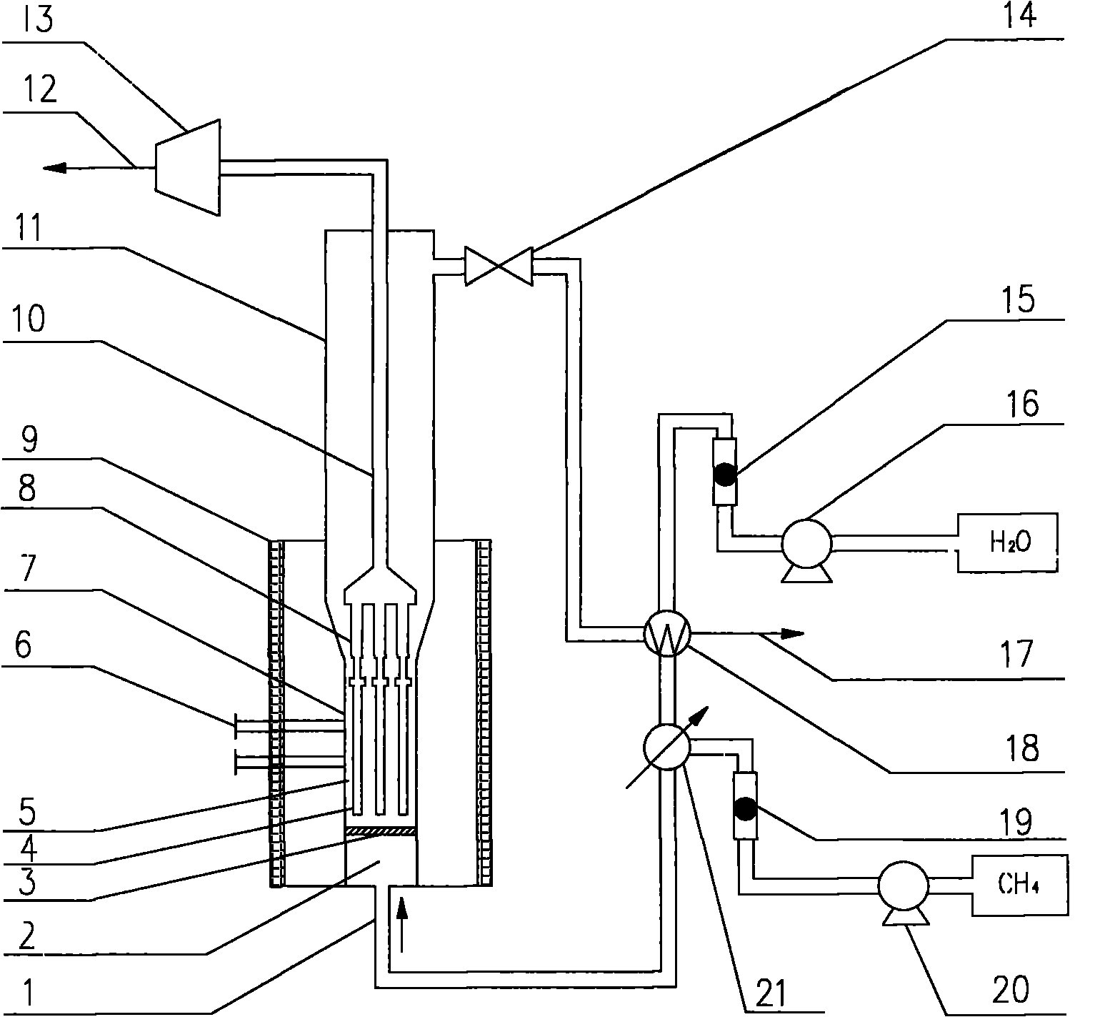
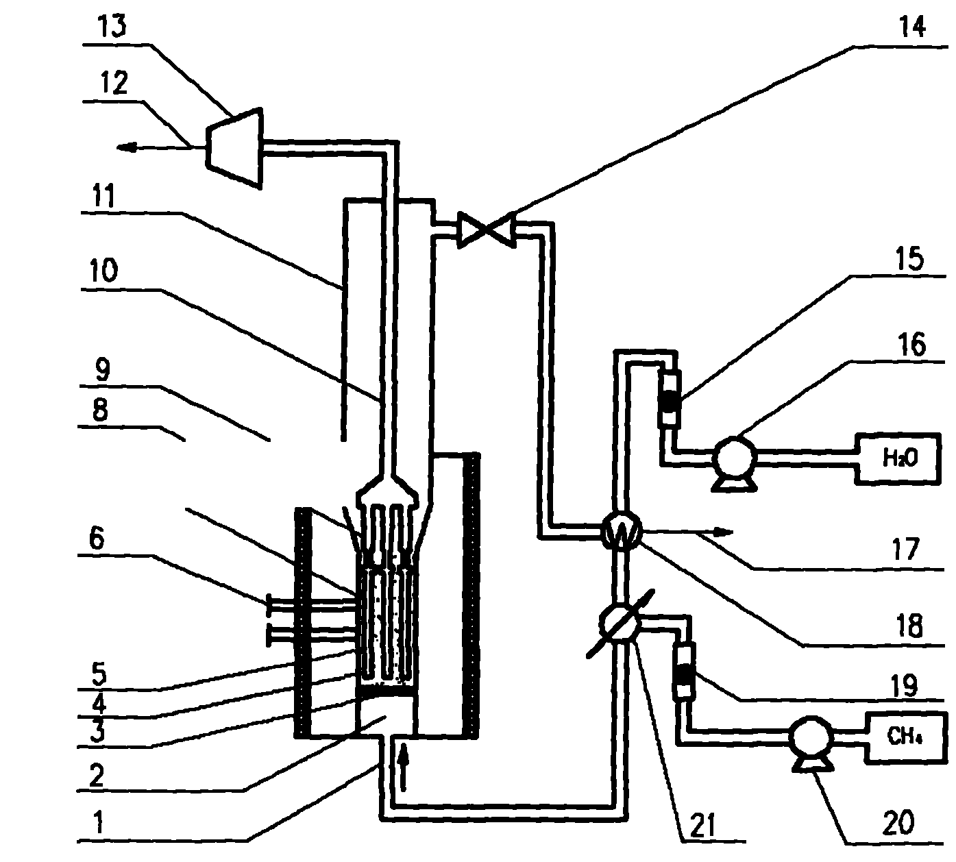
[0016] The main structure of this embodiment includes a raw material gas inlet 1, a pre-distribution chamber 2, a gas distribution plate 3, a palladium membrane module 4, a catalyst bed 5, a sampling port 6, a reaction zone bed 7, a metal connecting pipe 8, and a heating system 9 , hydrogen conduit 10, expansion section 11, ultra-pure hydrogen outlet 12, vacuum pump 13, back pressure valve 14, liquid rotameter 15, water pump 16, tail gas outlet 17, heat exchanger 18, gas rotameter 19, gas pump 20 And the preheater 21, the components are combined to form a hydrogen selective membrane fluidized bed methane steam reforming hydrogen production device or reactor; the bottom of the device is equipped with a raw material gas inlet 1, and a pre-distribution chamber is arranged on the upper part of the raw material gas inlet 1 2. A gas distribution plate 3 is formed between the pre-distribution chamber 2 and the bed body 7 in the fluidized bed reaction zone, and the pre-distribution cha...


PUM

PropertyMeasurementUnit
diameteraaaaaaaaaa
areaaaaaaaaaaa
particle diameteraaaaaaaaaa

Abstract

The invention belongs to the technical field of chemical equipment, and relates to a method for producing hydrogen through coupled catalytic reforming and membrane separation reaction, and a device thereof, in particular to a method for producing hydrogen through fluidized-bed methane steam reforming, and a device thereof, which apply to the fields of petroleum, chemical industry and fuel cells. A main structure comprises a feed gas inlet, a pre-distribution chamber, a gas distribution plate, a palladium membrane component, a catalyst bed layer, a sampling port, a fluidized-bed reaction-zone bed body, a metal connection tube, a heating system, a hydrogen duct, an expansion section, a super pure hydrogen outlet, a vacuum pump, a backpressure valve, a liquid rotor flow meter, a water pump, an exhaust gas outlet, a heat exchanger, a gas rotor flow meter, a gas pump and a preheater, wherein the components are in gas-liquid communication and organic coordination to form a methane steam reforming hydrogen production device or reactor with a hydrogen selective membrane fluidized bed, and the top of the fluidized-bed reaction-zone bed body is sealed by adopting a cover-type structure. The invention has the advantages of simple process, low investment in equipment, good membrane separation performance and high hydrogen production rate.

Description

Technical field: [0001] The invention belongs to the technical field of chemical equipment, and relates to a method for producing hydrogen by coupling catalytic reforming and membrane separation reaction and its device, in particular to a method for producing hydrogen by using membrane fluidized bed methane steam reforming and its device, which is suitable for petroleum , chemical and fuel cell fields. Background technique: [0002] With the rise of fuel cell vehicles, hydrogen energy, as a clean, efficient, safe, and sustainable energy source, is regarded as the energy source with the most development potential in this century. Methane steam reforming is also a hydrogen production method commonly used in industry at present. . At present, the traditional methane steam reforming reactor uses a fixed bed, and pressure swing adsorption is the most commonly used hydrogen purification technology. Due to the large heat transfer and diffusion resistance of the fixed bed, and the ...

Claims


Application Information

Patent Timeline
Patent Type & Authority Applications(China)
IPC IPC(8): C01B3/44C01B3/50
Inventor 郭庆杰侯良玉王许云耿启金徐东彦赵书菊杨振楠
Owner QINGDAO UNIV OF SCI & TECH
Why Eureka
Try Eureka