LED light source with heat dissipation device and processing method thereof

A technology of LED light source and heat dissipation device, which is applied in the parts of lighting device, light source, cooling/heating device of lighting device, etc. The effect of poor contact, simplified process flow, and guaranteed life

Inactive Publication Date: 2010-09-22
ZHEJIANG MANELUX LIGHTING
View PDF0 Cites 15 Cited by
  • Summary
  • Abstract
  • Description
  • Claims
  • Application Information

AI Technical Summary

Problems solved by technology

However, in addition to the requirements for light intensity and light color of ordinary lamps, LED lights also have a very important feature of heat dissipation, and the lights can only rely on air convection heat dissipation and tiny radiation heat dissipation, which leads to large LED lights. , a heavy defect
I have applied for an invention patent called "LED lamp heat dissipation device and its processing method", and proposed the method of using heat sinks to clamp after plugging, which greatly reduces the weight and volume of LED lamps, but there is still room for improvement. Improvements and improvements, among them, the LED chip and the heat sink are two independent components, and there is thermal resistance at the junction of the two, which affects the quality improvement of the LED lamp

Method used


Image

  • LED light source with heat dissipation device and processing method thereof
  • LED light source with heat dissipation device and processing method thereof
  • LED light source with heat dissipation device and processing method thereof

Examples


Embodiment 1

[0056] Now, a 3W white LED light source is specifically manufactured by using the method of integrating the LED chip 3 and the heat dissipation device in the present invention,

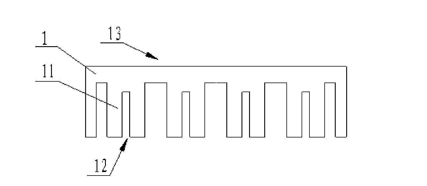
[0057] The manufacture of the LED base 1 applies the method described in the patent "radiation device", we adopt such as Figure 7 The LED base 1 of the structure shown. The front is a diameter? 2, with 6 ribs 11 on the back and 4 ribs 11 in the middle, each rib 11 has a 0.6mm cooling groove 12 in the middle, which is used to insert a carbon nano heat sink 2 with a thickness of 0.5mm or other Heat sink 2 of high thermal conductivity material. The height of the heat sink 2 is determined according to the requirements of heat dissipation and the conditions allowed by the lamp body. In this example, the height is 4mm, and after the heat sink 2 is inserted, press it and the rib 11 mechanically.

[0058] On the front of the base 1, the pattern for installing the LED chip 3 is made in the same way as mak...

Embodiment 2

[0061] Adopt the method of the present invention, make a 7W blue light LED.

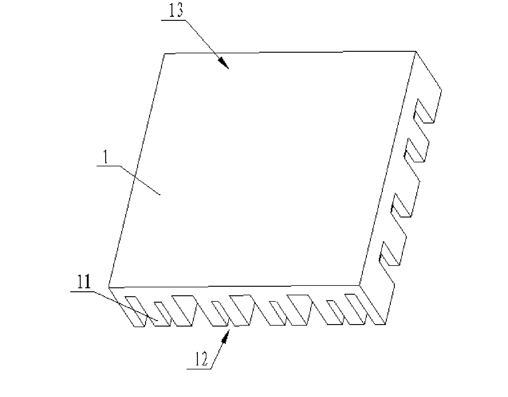
[0062] Because the power of the LED is much higher than that in Embodiment 1, the entire LED base 1 adopts the square base 1 shown in FIG. 1 . The size of the plane part of the square base 1 is 24mm×24mm, there are 6 ribs 11 on the back, the height is 2-10mm, and there are 4 ribs 11 in the middle, and there is a cooling groove 12 of 0.5-0.6mm in the middle of each rib 11. Same as in Example 1.

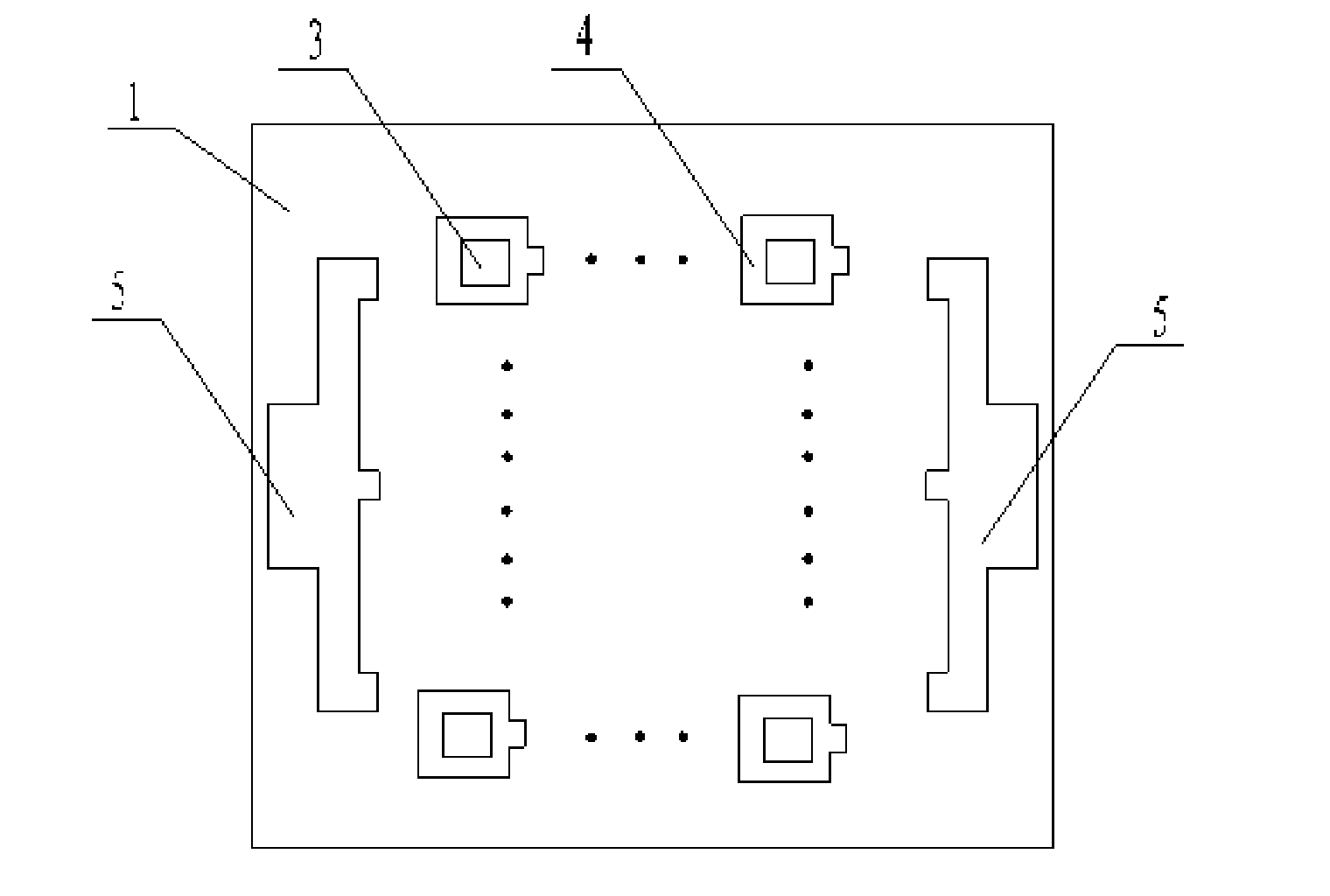
[0063] The front is also similar to Embodiment 1, and the chip 3 placement area is made. In this example, 38 14mil×14mil Blu-ray chips are arranged in a 9×9 matrix, all connected in series. As shown in Figure 2, corresponding to the square base 1, the surrounding frame 7 outside the mounting area of ​​the chip 3 is also made into a square shape and fixed on the base 1. The steps for making the LED light source are the same as in Embodiment 1 thereafter, except that The process of coating phosphor can be ch...

Embodiment 3

[0065] A variable color LED light source is produced by applying the method of the invention.

[0066] Currently on the market, color-changing LEDs are composed of three chips 3 of red, green and blue. In this embodiment, four chips 3 with emission wavelengths of 455nm, 525nm, 585nm and 630nm are used to form an LED light source capable of changing the emission color.

[0067] In this embodiment, the structure of the LED base 1 is exactly the same as that in Embodiment 2. In the distribution of the chip 3, we use 18 chips 3 with a luminous wavelength of 455nm, 27 chips 3 with a luminous wavelength of 525nm, 18 chips 3 with a luminous wavelength of 585nm, and 18 chips 3 with a luminous wavelength of 630nm, and each chip 3 electrodes are respectively drawn. Four current-adjustable power supplies are used to respectively drive the LED chips 3 of four light colors to emit light. A variety of colors can be obtained by matching different currents in each group.

[0068]The above-...


PUM


Abstract

The invention discloses an LED light source with a heat dissipation device and a processing method thereof, relating to an LED light source. The conventional LED light source has low heat dissipation efficiency, large size, heavy weight and more production procedures. The LED light source comprises a base, a plurality of LED chips arranged on the upper surface of the base and an electrode lead-out region which is convenient to connect a driving power supply. The LED light source is characterized in that a convex rib is arranged at the lower part of the base in an extension way, a heat radiation tank is arranged in the middle of the convex rib, an LED chip supporting body is arranged at the upper part of the base, and the heat dissipation device is arranged at the lower part of the base. Differing from an LED light source and heat dissipation device split structure in the prior art, the invention prevents the thermal resistance between the LED light source and the heat dissipation device from generating, greatly improves the heat dissipation efficiency because heat generated during the working process of the LED chips is directly transferred to heat dissipation fins through the base and heat resistance layers, such as an adhesion layer, and the like is not arranged between the LED light source and the heat dissipation device, improves the heat dissipation and the quality of an LED lamp, reduces the size of a lamp body for accommodating LEDs, and can ensure that the product is standardized and serialized, and has less working procedures and high processing efficiency.

Description

Technical field] [0001] The invention relates to an LED light source, especially an LED light source with a cooling device and a processing method thereof. 【Background technique】 [0002] Because LED lights are in line with the direction of low-carbon economy, many lighting factories have switched to producing LED lights. The LED lamps produced in the market can be divided into two categories from a technical point of view: one is a combination of low-power LEDs, for example, three 1W LEDs are placed in an equilateral triangle, and a cover is added to form a lamp. From the outside, the light it emits is uniform. In fact, on its illuminated surface, the distribution of light is uneven. Working under such light can easily cause visual fatigue and damage people's eyesight. [0003] The other is a lamp made of an LED light source made by an integrated packaging method. Because this lamp has only one illuminant, the consistency and uniformity of the illumination are relatively...

Claims


Application Information

Patent Timeline
Patent Type & Authority Applications(China)
IPC IPC(8): F21S2/00F21V29/00F21V17/00F21V23/00F21V9/08F21Y101/02F21V29/503F21V29/77
Inventor 楼满娥郭邦俊王铨海
Owner ZHEJIANG MANELUX LIGHTING
Why Eureka
Try Eureka