Dynamic compensation circuit with ultra-low power consumption and linear regulator with the same

A linear regulator and dynamic compensation technology, applied in the direction of adjusting electrical variables, control/regulation systems, instruments, etc., can solve the problems of large noise introduced into the system, difficulty in realizing non-capacitor work, high process requirements, etc., and achieve chip area and Low power consumption, practical total power consumption, and cost reduction effect

Inactive Publication Date: 2010-09-29
广州市广晟微电子有限公司
View PDF5 Cites 43 Cited by
  • Summary
  • Abstract
  • Description
  • Claims
  • Application Information

AI Technical Summary

Problems solved by technology

However, there are more or less deficiencies in the current technologies, such as the method of using an output device with low on-resistance, which requires higher process requirements, or requires the use of charge pump technology to introduce greater noise to the system; The zero point compensation technology is either limited by cost and accuracy, or it is difficult to achieve true capacitor-free operation; the active capacitor technology has complex circuits and unacceptable power consumption, and the more commonly used Miller compensation technology is often due to the addition of additional op amp increases circuit complexity and power consumption

Method used


Image

  • Dynamic compensation circuit with ultra-low power consumption and linear regulator with the same
  • Dynamic compensation circuit with ultra-low power consumption and linear regulator with the same
  • Dynamic compensation circuit with ultra-low power consumption and linear regulator with the same

Examples


Embodiment Construction

[0026] The Miller effect (Miller effect) means that in the amplifying circuit, the distributed capacitance or parasitic capacitance between the input and the output is due to the amplification of the amplifier, and its equivalent capacitance value at the input end will be enlarged by 1+K times, where K is the Stage amplifier circuit voltage magnification. The Miller effect is named after John Milton Miller. In 1919 or 1920, Miller discovered this effect when studying vacuum tube triodes, but this effect also applies to modern semiconductor triodes.

[0027] Miller compensation: A compensation method using the Miller effect, which can use a smaller capacitance value to obtain the compensation effect of a larger equivalent capacitance.

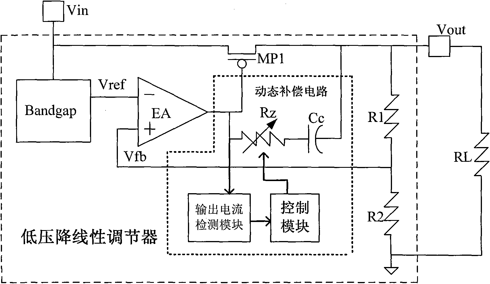
[0028] refer to figure 2 , an ultra-low power dynamic compensation circuit, including:

[0029] A dynamic Miller compensation module, which is used to change the zero position of the compensation;

[0030] An output current detection module...


PUM


Abstract

The invention discloses a dynamic compensation circuit with ultra-low power consumption and a linear regulator with the same. The dynamic compensation circuit comprises a dynamic compensation module, a current output detection module and a control module. In the linear regulator applied with the dynamic compensation circuit with ultra-low power consumption, the dynamic compensation circuit with ultra-low power consumption is connected between the output end of an error amplifier and the output end of the linear regulator. The dynamic compensation circuit with ultra-low power consumption and a linear regulator with the same of the invention have very simple structures and practicality, can effectively ensure the stable work under the application condition of a variety of output load. The dynamic compensation circuit only has ultra-low power consumption less than 1mu A, and reduces the cost of production and application of chips due to the small occupied chip area. The dynamic compensation circuit with ultra-low power consumption and the linear regulator with the same of the invention are widely applicable to power management application process.

Description

technical field [0001] The invention relates to a compensation circuit and a linear regulator, in particular to an ultra-low power consumption dynamic compensation circuit and a linear regulator using the circuit. Background technique [0002] Low drop-out linear regulator (LDO: Low Drop-out Regulator) is an important branch of power management chips. Compared with switching power supply technology, low drop-out linear regulator has simple structure, low cost, low noise, low power consumption and no Electromagnetic interference and other advantages, so it is widely used in portable electronic systems. [0003] Such as figure 1 As shown, a traditional low-dropout linear regulator is composed of a reference generation module, an error amplifier, an output device and a resistor divider network, and the load resistor RL and the load capacitor CL together form the load of the linear regulator. The reference generating module generates a bandgap (bandgap) reference voltage Vref ...

Claims


Application Information

Patent Timeline
Patent Type & Authority Applications(China)
IPC IPC(8): G05F1/565
Inventor 徐肯张建强
Owner 广州市广晟微电子有限公司
Why Eureka
Try Eureka