Preparation method and equipment of screw drill inside spin pre-outline stator
A technology of contour stator and screw drilling tool, which is applied to electric processing equipment, metal processing equipment, electrochemical processing equipment, etc., can solve the problems of poor temperature resistance, low motor output torque, unstable work, etc., and achieve long service life. , The output torque is high and the work is stable.
- Summary
- Abstract
- Description
- Claims
- Application Information
AI Technical Summary
Problems solved by technology
Method used
Image

Examples
Embodiment 1
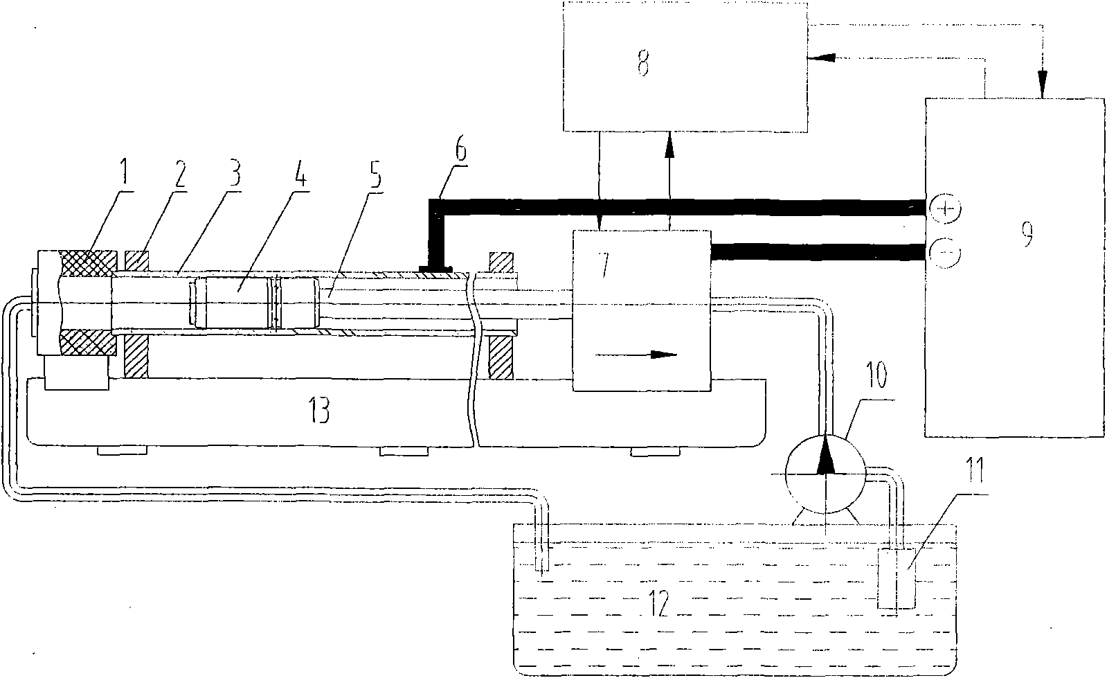
[0025] see figure 1 The present invention adopts the pull-type method to prepare the inner helical pre-contour stator of the screw drilling tool. The present invention is composed of an electrolysis machine tool. The electrolysis machine tool includes: conductive copper bar 6, numerical control cabinet 8, power supply 9, electrolyte pump 10, filter screen 11, Liquid pool 12, bed 13, rear seal 1 is arranged on the tailstock of the electrolysis machine tool, clamp 2 is arranged on the bed 13 of the electrolysis machine tool between the rear seal 1 and the head box 7, and the prefabricated pipe 3 before electric machining is clamped on On the fixture 2, a cathode 4 is provided at one end of the cathode rod 5, and the other end is connected with the bedside box 7. The cathode 4 is divided into a working part and a guiding part, the guiding part is a cylinder with the same diameter, the working part is conical, and the outer surface of the conical shape is composed of spiral plum p...
Embodiment 2
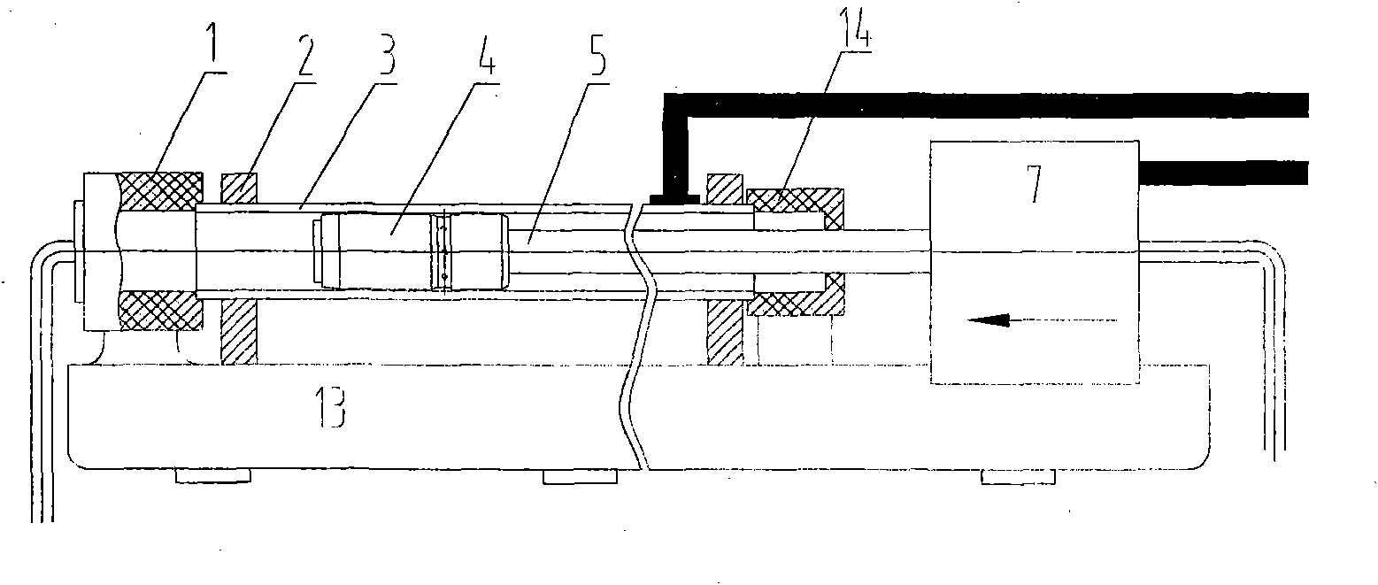
[0033] see figure 2 The present invention adopts the push type method to prepare the inner helical pre-contour stator of the screw drilling tool. The present invention is composed of an electrolysis machine tool, which includes: conductive copper bar 6, numerical control cabinet 8, power supply 9, electrolyte pump 10, filter screen 11, electrolytic Liquid pool 12, bed 13, rear seal 1 is arranged on the tailstock of the electrolysis machine tool, clamp 2 is arranged on the bed 13 of the electrolysis machine tool between the rear seal 1 and the head box 7, and the prefabricated pipe 3 before electric machining is clamped on On the fixture 2, one end of the prefabricated tube 3 before electric processing is located at the rear seal 1, and the other end is provided with a seal 14, and one end of the cathode rod 5 is provided with a cathode 4, and the other end is connected with the bedside box 7, and the cathode 4 is divided into a working part and a guide The guide part is a cyl...
PUM
| Property | Measurement | Unit |
|---|---|---|
| Current density | aaaaa | aaaaa |
| Pressure | aaaaa | aaaaa |
| Current density | aaaaa | aaaaa |
Abstract
Description
Claims
Application Information