
Radio frequency receiving and transmitting front end for millimeter wave holographic imaging security check system

A radio frequency transceiver and holographic imaging technology, which is used in radio wave measurement systems, reflection/re-radiation of radio waves, and electrical/magnetic detection for logging records. , high cost, to achieve the effect of strong anti-electromagnetic radiation ability, large dynamic range and small circuit loss

Active Publication Date: 2010-10-20
杭州芯影科技有限公司
View PDF5 Cites 34 Cited by
  • Summary
  • Abstract
  • Description
  • Claims
  • Application Information

AI Technical Summary

Problems solved by technology

The front-end uses an additional voltage-controlled oscillator and mixer to down-convert the RF signal to the intermediate frequency band, then performs quadrature mixing in the intermediate frequency band, and outputs I / Q signals. Therefore, the voltage-controlled oscillation used in the front-end There are more than one mixer and mixer, and the number of components is large; at the same time, the system is based on the waveguide structure, so the volume is large, the weight is heavy, the cost is high, and the product consistency is not good enough

Method used


Image

  • Radio frequency receiving and transmitting front end for millimeter wave holographic imaging security check system
  • Radio frequency receiving and transmitting front end for millimeter wave holographic imaging security check system
  • Radio frequency receiving and transmitting front end for millimeter wave holographic imaging security check system

Examples


Embodiment Construction

[0025] Below in conjunction with specific embodiment, further illustrate the present invention. It should be understood that these examples are only used to illustrate the present invention and are not intended to limit the scope of the present invention. In addition, it should be understood that after reading the teachings of the present invention, those skilled in the art can make various changes or modifications to the present invention, and these equivalent forms also fall within the scope defined by the appended claims of the present application.

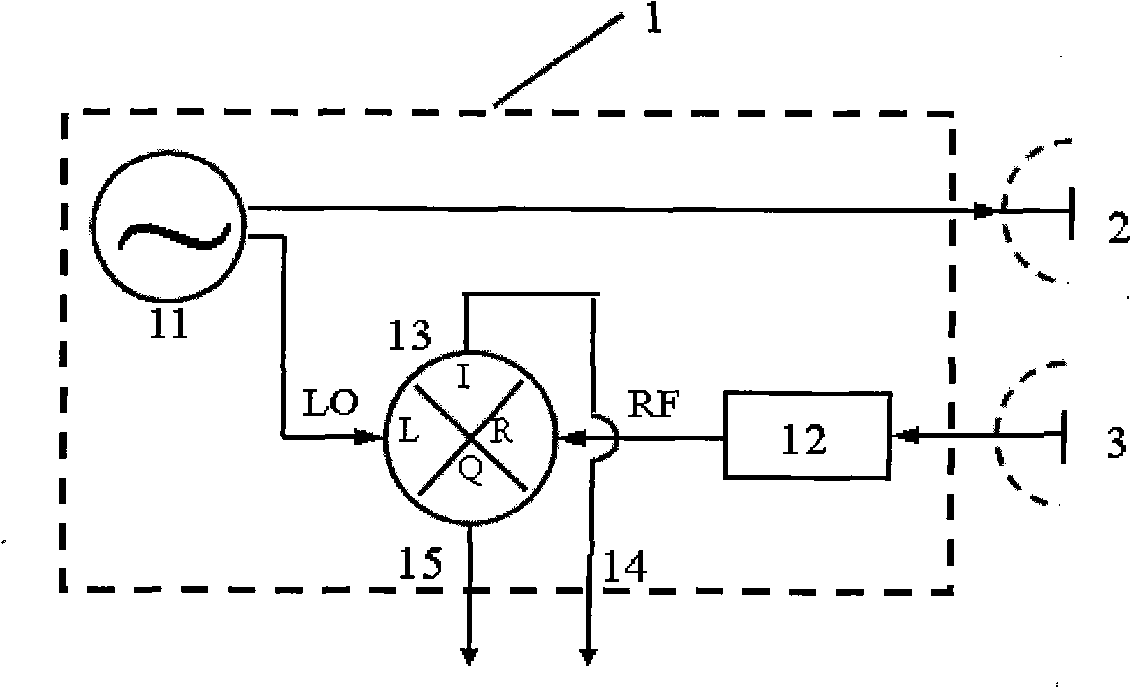
[0026] The embodiment of the present invention relates to a radio frequency transceiver front-end for a millimeter-wave holographic imaging security inspection system, which adopts a differential system and uses a millimeter-wave voltage-controlled oscillator (referred to as "millimeter-wave VCO") to generate a broadband, high-power, high-phase The stable and high linearity millimeter wave signal source transmits millimeter wav...


PUM


Abstract

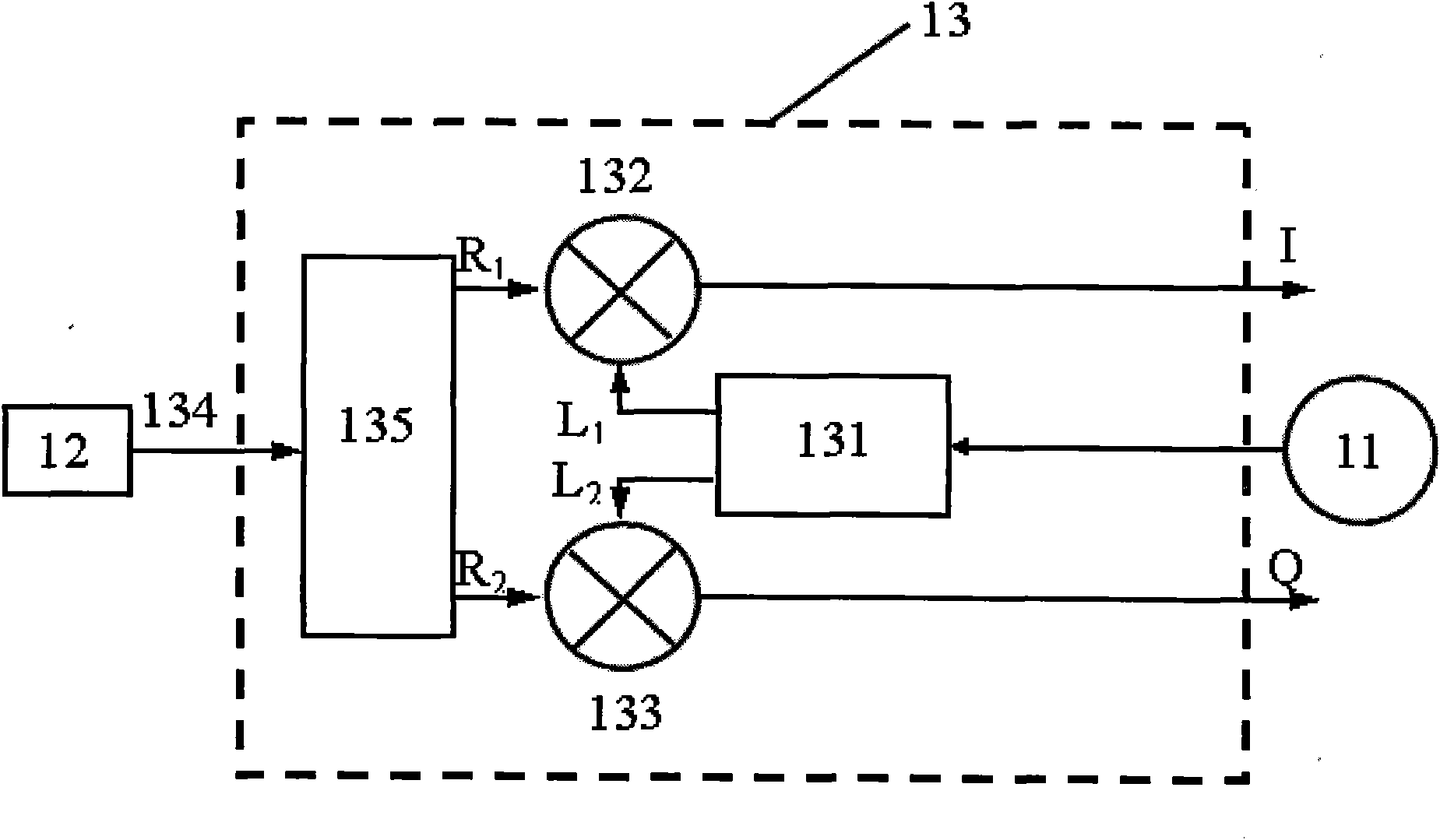
The invention relates to a radio frequency receiving and transmitting front end for a millimeter wave holographic imaging security check system, which comprises a millimeter wave voltage-controlled oscillator, a millimeter wave low-nose amplifier and a millimeter wave quadrature mixer, wherein the millimeter wave voltage-controlled oscillator is connected with the millimeter wave quadrature mixer; the millimeter wave low-nose amplifier is connected with the millimeter wave quadrature mixer; the millimeter wave voltage-controlled oscillator is used for generating a millimeter wave radio frequency signal to be transmitted to a target and a local oscillation signal to be fed back to the millimeter wave quadrature mixer directly; the millimeter wave low-nose amplifier is used for receiving the radio frequency signal carrying the scatter amplitude and phase information of the target to perform low-noise amplification; and the millimeter wave quadrature mixer is used for performing the quadrature mixing of the millimeter wave local oscillation signal directly fed back by the millimeter wave voltage-controlled oscillator and the radio frequency signal amplified by the millimeter wave low-nose amplifier. In the invention, after necessary preamplification and digital sampling treatment of the output signal, the millimeter wave holographic image of the target can be restored by using a millimeter wave holographic algorithm.

Description

technical field [0001] The invention relates to the fields of security inspection technology and millimeter-wave holographic imaging technology, in particular to a radio frequency transceiver front-end used in a millimeter-wave holographic imaging security inspection system. Background technique [0002] The current millimeter-wave holographic imaging security inspection system is mainly based on the years of research on millimeter-wave holographic imaging technology by scholars such as David M.Sheen and Douglas L.McMakin of the Pacific Northwest National Laboratory (PNNL), and is held by L-3 Communications in the United States. Manufactured by the company, it has been put into partial use in some sensitive airports in the United States. The millimeter-wave holographic imaging security inspection system has the technical characteristics of broadband, real-time, and three-dimensional holography. In the application of airport security inspection, it can penetrate human clothin...

Claims


Application Information

Patent Timeline
Patent Type & Authority Applications(China)
IPC IPC(8): G01V3/30G01S7/02G01S13/89
Inventor 时翔孙晓玮钱蓉孙浩李凌云关福宏
Owner 杭州芯影科技有限公司
Learn More