Bulk silicon micro mechanic resonator and manufacturing method thereof

A silicon micromachine and silicon resonator technology, applied in resonator, microstructure technology, waveguide-type devices, etc., can solve the problems of high complexity and difficult processing technology, so as to reduce the production cost, reduce the process complexity, improve the effect on device performance

Active Publication Date: 2010-10-20
SHANGHAI INST OF MICROSYSTEM & INFORMATION TECH CHINESE ACAD OF SCI
View PDF3 Cites 35 Cited by
  • Summary
  • Abstract
  • Description
  • Claims
  • Application Information

AI Technical Summary

Problems solved by technology

[0013] Aiming at the problems existing in the processing of general silicon bulk resonators, especially the shortcomings of difficult and complicated processing technology, the present invention proposes a method for manufacturing bulk silicon micromechanical resonators

Method used


Image

  • Bulk silicon micro mechanic resonator and manufacturing method thereof
  • Bulk silicon micro mechanic resonator and manufacturing method thereof
  • Bulk silicon micro mechanic resonator and manufacturing method thereof

Examples


Embodiment 1

[0091] A layer of TiW / Au metal layer is deposited on both the resonator structure wafer and the cover plate wafer, and the metal layer on the structure wafer and the cover plate wafer is patterned by photolithography and etching. A layer of adhesive (adhesive can be glass paste, polymer or metal) is coated on the back of the silicon wafer by screen printing, and the adhesive is patterned, and the adhesive is used as a solder layer. The resonator device is electrically connected to the external circuit through the metal layer. The resistivity range of the substrate silicon wafer and the structural silicon wafer is 0.01-0.3Ω·cm, and the resistivity of the cover silicon wafer is not required, which is an ordinary silicon wafer. The main process steps include:

[0092] (1) On the polished heavily doped single crystal silicon wafer, the bottom cavity for the release of the resonator structure is fabricated by oxidation, photolithography, and silicon anisotropic wet etching process...

Embodiment 2

[0106] The cover plate silicon wafer is made of lightly doped N-type silicon wafer, and the P+ region is formed on the cover plate silicon wafer through methods such as oxidation, gluing photolithography, silicon oxide corrosion, and ion implantation. A layer of TiW / Au metal layer is deposited on both the resonator structure wafer and the cover plate wafer, and the metal layer on the structure wafer and the cover plate wafer is patterned by photolithography and etching. A layer of adhesive (adhesive can be glass paste, polymer or metal) is coated on the back of the silicon wafer by screen printing, and the adhesive is patterned, and the adhesive is used as a solder layer. The resonator device is electrically connected to the external circuit through the P+ region. The resistivity range of the substrate silicon wafer and the structural silicon wafer is 0.01-0.3Ω·cm, and the resistivity range of the cover silicon wafer is 0.01-1Ω·cm. The main process steps include:

[0107] (1...

Embodiment 3

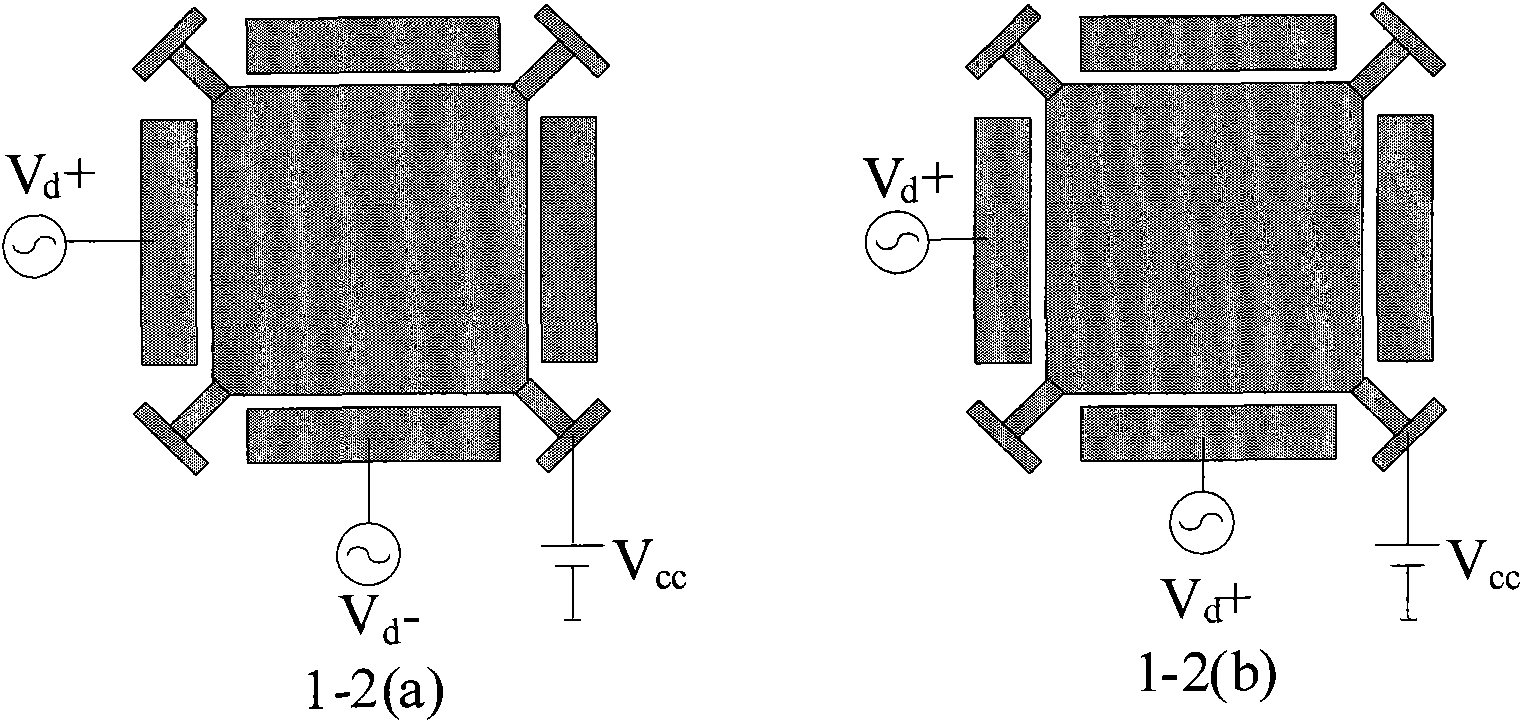
[0122] The substrate silicon wafer and structural silicon wafer of the bulk silicon resonator adopt low-resistance silicon wafers, the resistivity range of the substrate silicon wafer and structural silicon wafer is 0.01-0.3Ω·cm, and the cover silicon wafer is an ordinary silicon wafer. In order to enhance the strength of the driving signal and the detection signal, and further improve the performance of the resonator, the resonant oscillators of the two bulk silicon micromechanical resonators can be connected together through a beam coupling. Its specific embodiment is identical with embodiment 1. The main differences are: (1) different resonator oscillators: the oscillator of the resonator in embodiment 1 is a square plate, and the oscillator of the resonator in this embodiment is a figure in which two square plates are connected by a beam, see Figure 1-5 (a); (2) Different driving electrodes: the resonator in embodiment 1 has four electrodes symmetrically distributed around...


PUM

PropertyMeasurementUnit
electrical resistivityaaaaaaaaaa

Abstract

The invention relates to a bulk silicon micro mechanic resonator and a manufacturing method thereof. The invention is characterized in that: the resonator is formed by bonding a substrate silicon chip, a structural silicon chip and a cover plate silicon chip, the front side of the substrate silicon chip bonded together with the back side of the structural silicon chip, and the front side of the structural silicon chip is bonded with the back side of the cover plate silicon chip; when the resonator is manufactured, a suspended structure, namely a cavity under a resonant vibration generator, ismanufactured first, then an element structural layer is formed above the cavity by bonding, next the element structure of the resonator is released during the manufacturing of the element structure of the resonator by a dry-method erosion, and finally the cover plate silicon chip is fixed above the structural silicon chip by using a vacuum wafer for alignment and bonding. Before the element structure is manufactured, the cavity under the resonator is corroded by a wet method and the wafer package is used for the vacuum sealing of the element.

Description

technical field [0001] The invention provides a bulk silicon micromechanical resonator and a manufacturing method thereof, more precisely relates to a bulk silicon resonator manufactured by MEMS and the like, and belongs to the technical field of bulk silicon micromechanical resonator processing and microfabrication. Background technique [0002] As the time reference source in the circuit system, the clock chip plays an important role in the circuit system. Traditional clock chips generally use quartz crystal oscillators as resonators to generate signal waveforms. However, the quartz crystal oscillator is generally produced by cutting process, which makes it difficult to reduce its volume, which hinders the miniaturization of the circuit system. In addition, the quartz crystal oscillator cannot be integrated with the circuit system, which increases the production cost. In recent years, due to the development of micromachining technology, MEMS micromechanical resonators hav...

Claims


Application Information

Patent Timeline
Patent Type & Authority Applications(China)
IPC IPC(8): H01P7/06H01P11/00B81B3/00B81C1/00
Inventor 熊斌吴国强徐德辉王跃林
Owner SHANGHAI INST OF MICROSYSTEM & INFORMATION TECH CHINESE ACAD OF SCI
Why Eureka
Try Eureka