
Intermediate-pressure control two-position variable axial plunger hydraulic motor

A hydraulic motor and variable technology, which is applied in the direction of servo motor components, fluid pressure actuators, mechanical equipment, etc., can solve the problems of low control pressure, large piston size, fast response speed of variable hydraulic cylinder, etc., to achieve optimized external dimensions, The effect of stabilizing handling performance and reducing sensitivity

Inactive Publication Date: 2010-10-27
SAUER SHANGHAI HYDROSTATIC TRANSMISSION
View PDF6 Cites 23 Cited by
  • Summary
  • Abstract
  • Description
  • Claims
  • Application Information

AI Technical Summary

Problems solved by technology

However, the use of high system pressure to control the variable hydraulic cylinder causes the response speed of the variable hydraulic cylinder to be too fast, which makes the control performance of the two-position variable axial piston hydraulic motor unstable. Sometimes a damper is used in the variable control system to obtain a certain Control the speed, but the aperture size of the damper is very small, usually 0.2mm ~ 0.5mm, which requires relatively high cleanliness of the system, making the control system too sensitive
Another current method is to use the low pressure of the system to drive the variable hydraulic cylinder of the two-position variable axial piston hydraulic motor. This method can obtain stable control performance, but the piston size of the variable hydraulic cylinder is large, which affects the overall performance of the motor. Size limits its use and because of its low control pressure, fast response is difficult

Method used


Image

  • Intermediate-pressure control two-position variable axial plunger hydraulic motor
  • Intermediate-pressure control two-position variable axial plunger hydraulic motor
  • Intermediate-pressure control two-position variable axial plunger hydraulic motor

Examples


Embodiment Construction

[0014] The specific implementation of the present invention will be further described below in conjunction with the accompanying drawings.

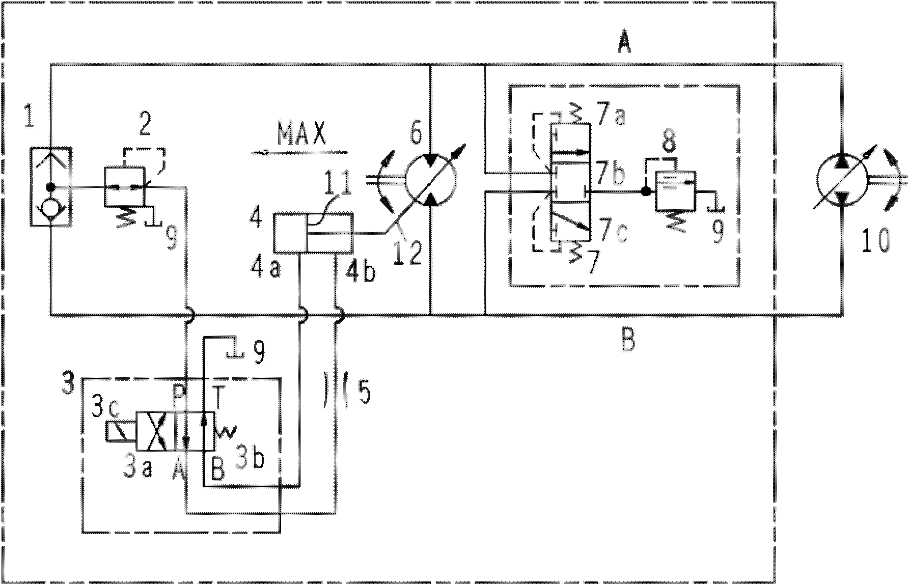
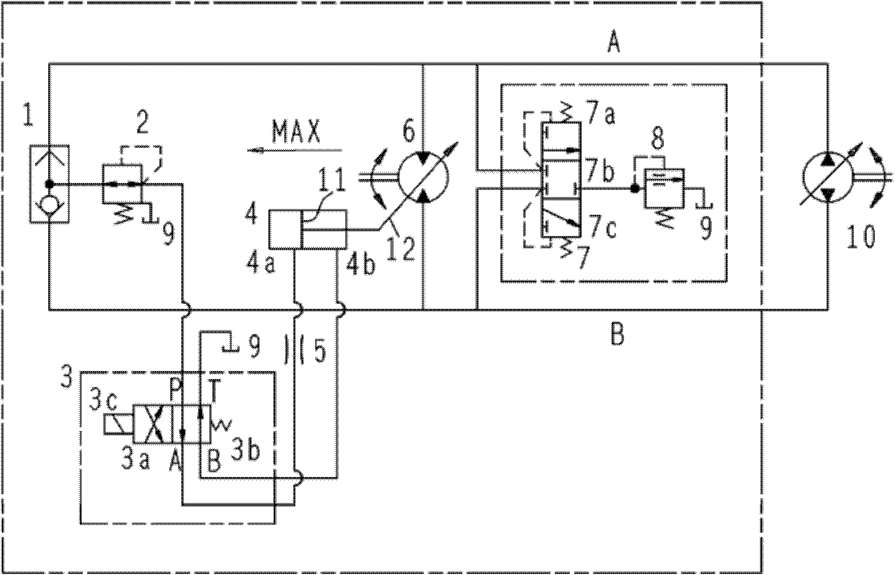
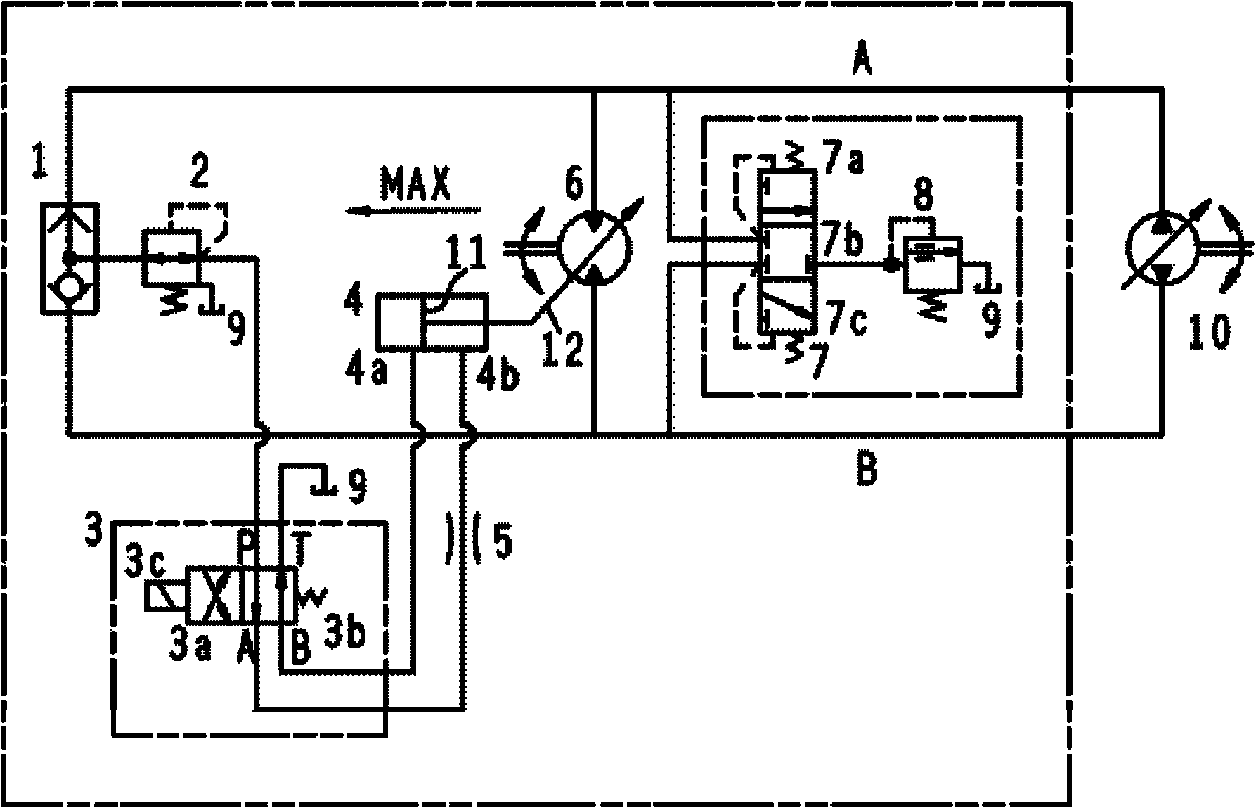
[0015] like figure 1 , figure 2 As shown, the present invention includes: a shuttle valve 1, a pressure reducing valve 2, a two-position four-way valve 3, a variable hydraulic cylinder 4, a damper 5, a variable axial plunger hydraulic motor 6, a flushing shuttle valve 7, and a flushing overflow valve 8.

[0016] When the initial position of the medium pressure control two-position variable axial piston hydraulic motor displacement is set at the maximum displacement, (such as figure 1 shown). The inlet of the variable axial piston hydraulic motor 6 is connected with the outlet of the variable hydraulic pump 10 , and the outlet of the variable axial piston hydraulic motor 6 is connected with the inlet of the variable hydraulic pump 10 . The two inlets of the shuttle valve 1 are respectively connected with the inlet and outlet of the va...


PUM


Abstract

The invention discloses an intermediate-pressure control two-position variable axial plunger hydraulic motor, which belongs to the technical field of hydraulics. The hydraulic motor comprises a shuttle valve, a reducing valve, a two-position four-way valve, a variable hydraulic cylinder, a damper, a variable axial plunger hydraulic motor, a washing shuttle valve and a washing overflow valve. The pressure of system high-pressure oil is reduced into an intermediate pressure by the shuttle valve and the reducing valve so as to drive a servo piston of the variable hydraulic cylinder to move. Due to the adoption of intermediate-pressure control, the hydraulic motor can simultaneously integrates the advantages of controlling the variable hydraulic cylinder by a system high pressure and a system low pressure so as to easily realize high-speed and low-speed adjustment in the conceptual design of the same variable motor, select relatively greater damper bore diameters, realize proper variable speeds, achieve a wider speed adjustment range and high control performance, and reduce the sensitivity of the variable hydraulic cylinder to pollution. An initial position of motor displacement can be randomly set to be a maximum or minimum displacement position according to the needs of clients. Due to the adoption of the hydraulic cylinder with a medium piston size, the overall dimension of the whole variable motor can be optimally designed.

Description

technical field [0001] The invention relates to a two-position variable axial plunger hydraulic motor, in particular to a two-position variable axial plunger hydraulic motor adopting a medium pressure control variable hydraulic cylinder, belonging to the technical field of hydraulic transmission. Background technique [0002] The hydraulic pump and the hydraulic motor constitute the energy conversion device in the hydraulic system. The former converts the mechanical energy of the prime mover into hydraulic energy of the liquid; the latter converts the hydraulic energy into mechanical energy output to perform the required action. A hydraulic motor is a hydraulic actuator that realizes continuous rotary motion. [0003] In terms of function, hydraulic pumps can be divided into variable displacement and non-variable displacement. A variable displacement hydraulic pump can output different flow rates at the same speed according to demand, and this type of pump is called a varia...

Claims


Application Information

Patent Timeline
IPC IPC(8): F15B15/18F15B13/02F15B15/20
Inventor 王晶程宇J·翰塞尔
Owner SAUER SHANGHAI HYDROSTATIC TRANSMISSION
Features
  • Generate Ideas
  • Intellectual Property
  • Life Sciences
  • Materials
  • Tech Scout
  • Unparalleled Data Quality
  • Higher Quality Content
  • 60% Fewer Hallucinations
Learn More