
Submersible servodrive system

A technology of dragging system and submersible oil, applied in the field of dragging system, can solve the problems of low motor speed, low motor efficiency and power factor, and oil production cost reducing system efficiency, etc.

Inactive Publication Date: 2010-11-03
杭州坤泽采油设备有限公司
View PDF1 Cites 9 Cited by
  • Summary
  • Abstract
  • Description
  • Claims
  • Application Information

AI Technical Summary

Problems solved by technology

[0003] First, when it is matched with centrifugal submersible pump, because the motor speed is lower than the synchronous speed, the motor efficiency and power factor are low
[0004] Second, when it is matched with the submersible screw pump, the speed is too high to reduce the speed to the speed suitable for the screw pump through the tachometer. Even if the reducer is used, the cost of oil production will be greatly increased and the efficiency of the system will be reduced. The frequency conversion speed control device is used to keep the motor in a low-frequency working state for a long time, and it is easy to cause the temperature rise of the motor to accelerate, causing motor failure
The system cannot realize flexible control, and the efficiency is low
[0005] Third, even if the traditional submersible electric pump system adopts frequency conversion control, its motor control cabinet is often placed on the ground. When the AC power is transmitted to the motor due to long-distance transmission, the energy loss is serious, which further reduces the efficiency of the system.
Although there is still the problem of low energy saving rate when combined with frequency conversion controller

Method used


Image

  • Submersible servodrive system
  • Submersible servodrive system
  • Submersible servodrive system

Examples


no. 1 example

[0131] Figure 20 is an exploded schematic view of the solution of the position detection device installed with two magnetic induction elements according to the first embodiment of the present invention. The position detection device includes parts such as inductive element 710, circuit board 711, magnetic conduction ring 712, stainless steel cover 713, magnetic steel ring 715 and casing (not shown), and magnetic steel ring 715 is installed on the motor tail shaft 716, and the rest can be Installed on the stainless steel cover 713 of the high-pressure threading sealing device 714 . The feature of this solution is that the position detection device has two magnetic induction elements, and the magnetic permeable ring 712 is also composed of two parts, one is a 1 / 4 magnetic ring, and the other is a 3 / 4 magnetic ring. Two incomplete magnetic rings form two slits for cooperating with two magnetic induction elements.

[0132] Figure 21 is a block diagram of a signal processing d...


PUM


Abstract

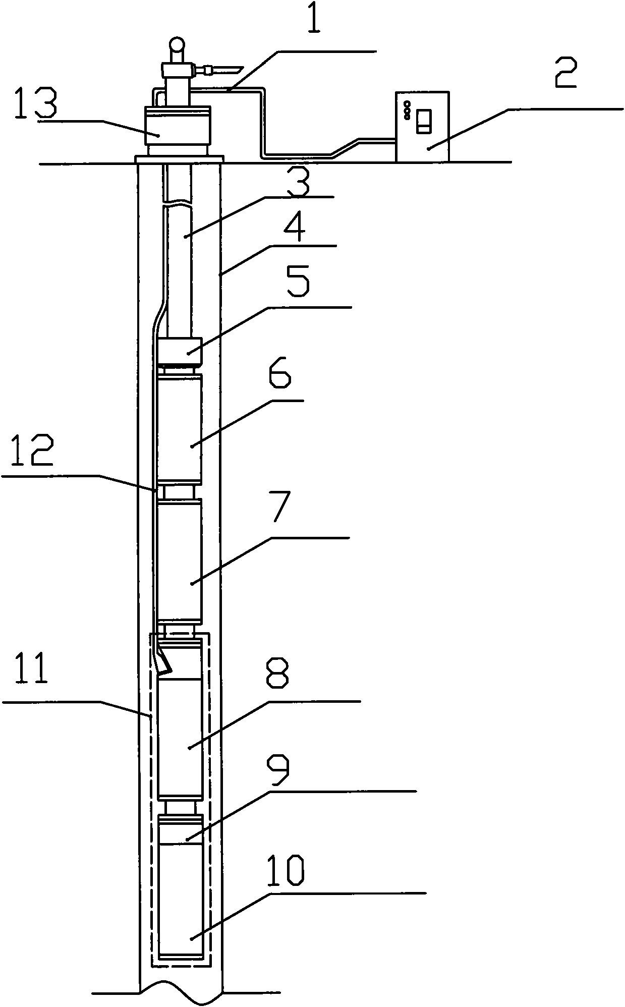
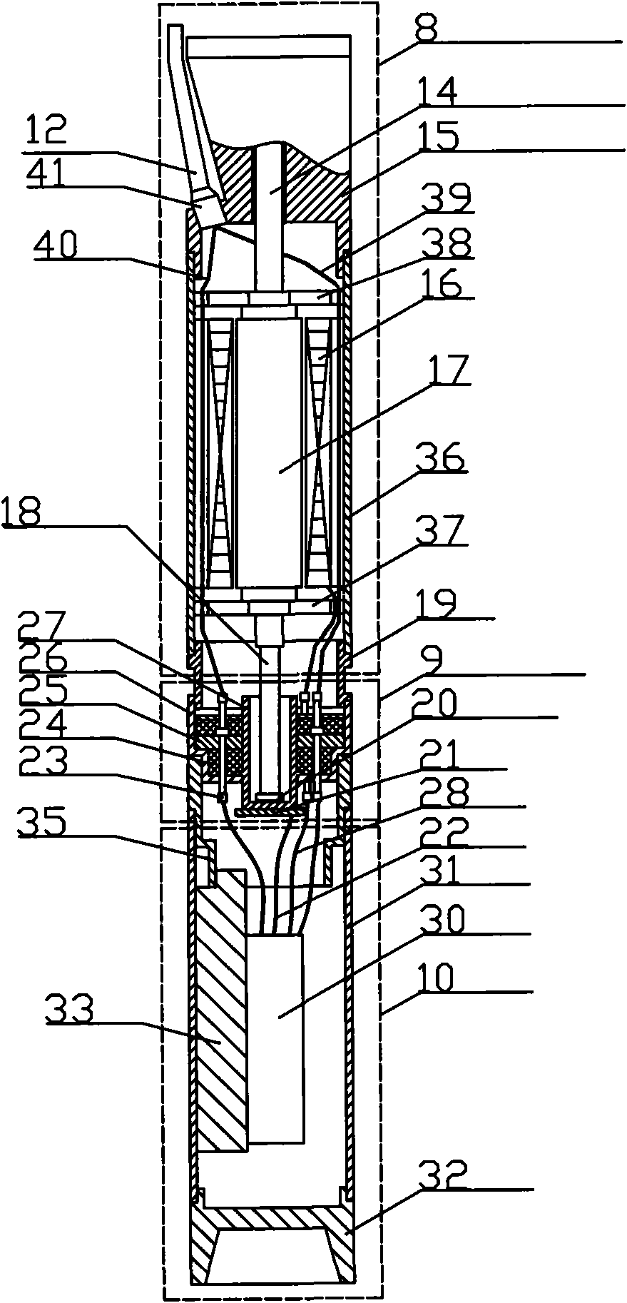
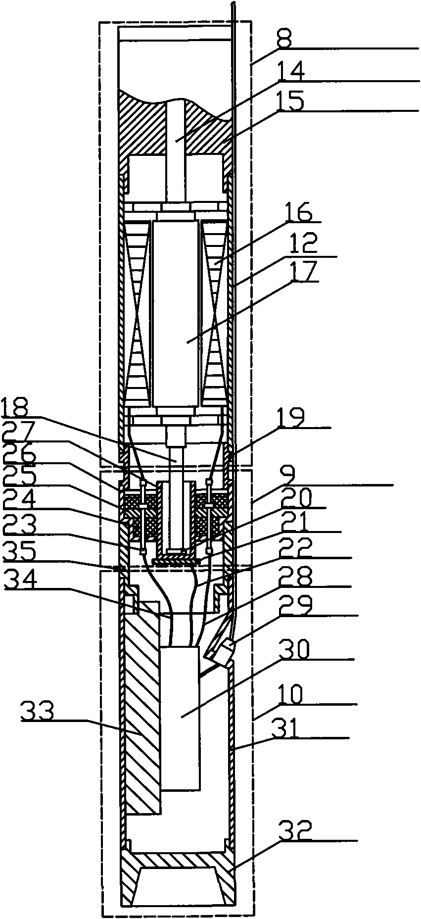
A submersible servodrive system comprises a pump. The system is characterized in that the pump is connected with a servo motor system by a protector; a ground control device is connected with ground power supply by a cable; the cable is connected with the servo motor system; the ground power supply is controlled by the ground control device to supply power to a servo motor and the pump; the servo motor system comprises the servo motor and a servo controller; a motor shaft of the servo motor is provided with a position detection device which outputs the position signal detected by the position detection device to the servo controller; the servo controller controls the servo motor to run; and the position detection device is fixed on the servo controller by a sealing device. The system has high power factor, high energy saving rate and high flexibility, further saves power, can realize flexible production and reduces the operation cost. When being started, a pumping unit can provide large torque, combine with soft start and reduce the power of a matching motor of the pumping unit.

Description

technical field [0001] The invention relates to a drag system, in particular to a submersible servo drag system. Background technique [0002] At present, in my country and other oil-producing countries in the world, submersible motors are widely used in oilfields to drive submersible electric pumps to draw crude oil. The power source of traditional electric submersible pump systems is mainly two-pole three-phase asynchronous motors. The oil production system has the following three problems in the matching of the oil production process: [0003] One is that when it is matched with a centrifugal submersible pump, because the motor speed is lower than the synchronous speed, the motor efficiency and power factor are low. [0004] Second, when it is matched with the submersible screw pump, the speed is too high to reduce the speed to the speed suitable for the screw pump through the tachometer. Even if the reducer is used, the cost of oil production will be greatly increased an...

Claims


Application Information

Patent Timeline
IPC IPC(8): H02P6/00G01D5/249
CPCG01D11/24
Inventor 郝双晖郝明晖
Owner 杭州坤泽采油设备有限公司
Learn More