A method of remediating contaminated water and apparatus for the same

A technology of polluted water and equipment, applied in the field of remediation of polluted water, which can solve problems such as complex storage technology, reduced permeability/water flux, and expensive treatment costs

Inactive Publication Date: 2010-11-03
THE UNIV COURT OF THE UNIV OF ABERDEEN REGENT WALK
View PDF0 Cites 3 Cited by
  • Summary
  • Abstract
  • Description
  • Claims
  • Application Information

AI Technical Summary

Problems solved by technology

But these treatments are expensive (HRC), require repeated applications (sodium lactate, whey), require complex storage techniques (whey) or reduce permeability / flux (ZVI, some coverings)

Method used


Image

  • A method of remediating contaminated water and apparatus for the same
  • A method of remediating contaminated water and apparatus for the same
  • A method of remediating contaminated water and apparatus for the same

Examples


Embodiment 1

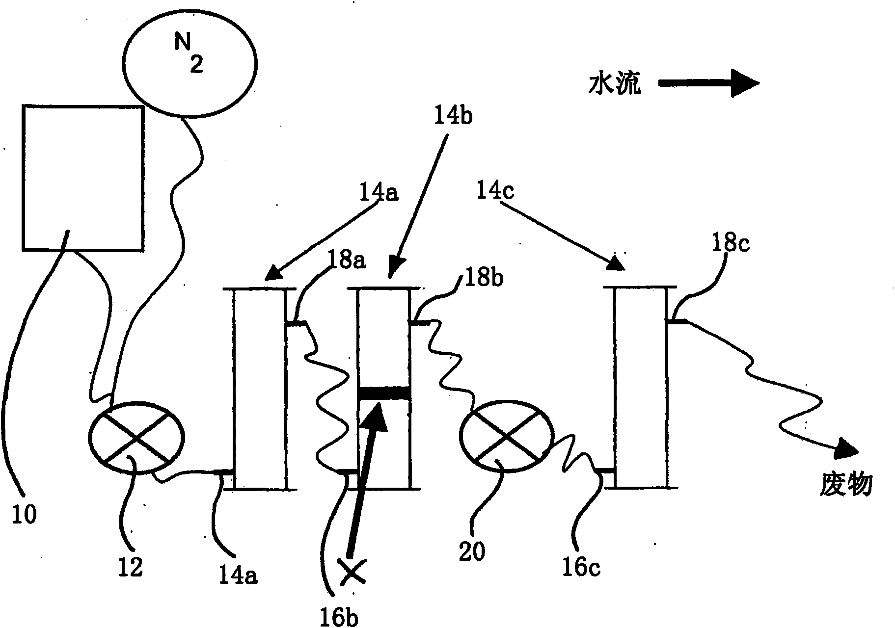
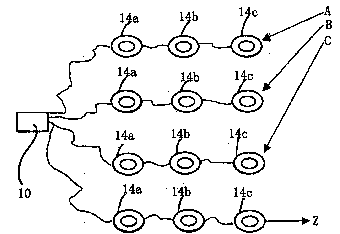
[0031] according to figure 1 Schematic design of the treatment train for the flow of water through the system is shown. A 20L reservoir 10 containing autoclaved distilled water was connected by PTFE tubing to a peristaltic pump 12 connected to three series-connected stainless steel columns 14a, 14b and 14c. Cylinders 14a, 14b and 14c consist of a stainless steel core with a diameter of 76 mm and a height of 300 mm and a stainless steel cap. Inlets 16a, 16b, and 16c and outlets 18a, 18b, and 18c were placed 20 mm from the top and bottom of each cylinder 14a, 14b, and 14c, and equipped with fine wire mesh ( figure 1 not shown) to prevent particle clogging. A further pump 20 is arranged between the outlet 18b and the inlet 16c. In each trial, three treatment series (labeled A, B, and C) and one control series (no treatment, labeled series Z) were run simultaneously, as figure 2 shown schematically.

[0032] The first and third columns (14a and 14c, respectively) of each ser...

Embodiment 2

[0037] Such as figure 2 As shown, treatment series A, B, C and Z were set up as described in Example 1 above. The experiment was carried out as described in Example 1 above, but with the water storage tank 10 free of contaminants, only distilled water. Instead, TCE is introduced directly by injection at inlet 16b, and only the sample analysis at points (iii) and (iv) described above is performed. The purpose of transmitting TCEs in this way is to characterize "source" TCEs, eg from direct spills or memory leaks.

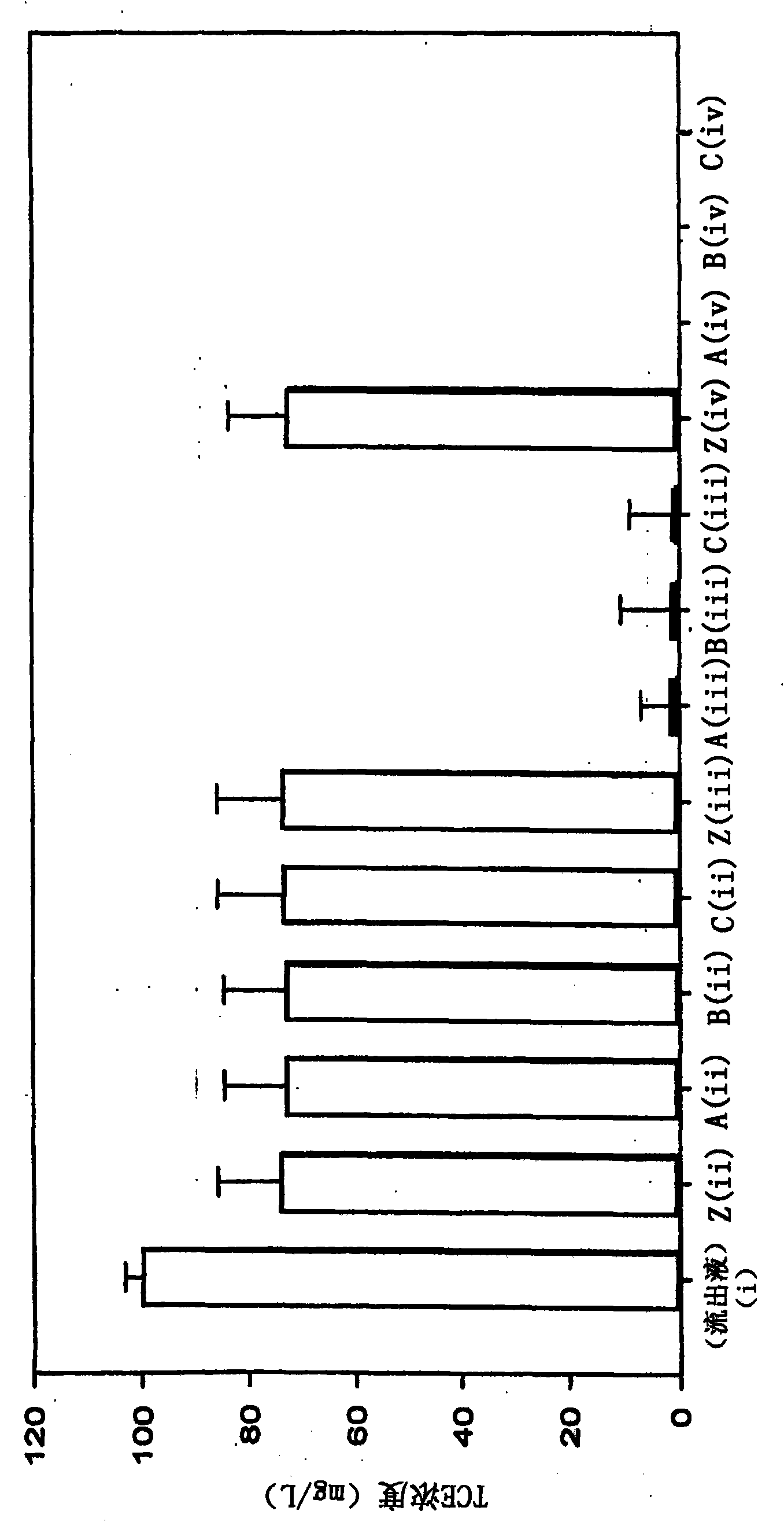
[0038] The TCE concentrations of the extracted samples are shown in Figure 4 middle. The concentration of the effluent from series Z was assigned 100%, ie the effluent was not subjected to debris treatment and passed through only three sand-filled cylinders. The final effluent had a TCE concentration of 1460 mg / L and the amount of TCE removed by residue treatment in series A, B and C was expressed as a percentage of this value.

[0039] Figure 4 It was shown...

Embodiment 3

[0041] Treatment series A, B, C and Z were set up as described above for Example 1. The experiment was carried out as described in Example 1 above, but wherein the storage tank 10 contained 6 different CAH pollutants, each at a concentration of 100 mg / L (PCE, TCE, dichloroethylene (DCE), carbon tetrachloride (CT), chloroform (CF) and trichloroethane (TCA)). Artificial groundwater samples were taken at points (i), (iii) and (iv) as described in Example 1.

[0042] The CAH concentrations of the extracted samples are shown in Figure 5 Middle (from left to right are the displayed results of PCE, TCE, DCE, TCA, CT and CF in each sample group). The results showed that the concentration of all six pollutants in series A, B and C showed significant reduction (P ≤ 0.05) compared with series Z. The greatest reduction in concentration was in samples containing CT and TCA, where a reduction of greater than 90% was recorded at all sampling points. The concentration of TCE was reduced ...


PUM


Abstract

A method of remediating contaminated water is disclosed, for example groundwater, surface water and waste water, for example groundwater contaminated with dissolved and free product phase hydrocarbons, metals, e.g. chromium and other transition metals, uranium, soluble components of petroleum hydrocarbons (BTEX), perchlorates, and hexahydro-1, 3, 5- trinitro-1, 3, 5-triazine (RDX), and in particular chlorinated hydrocarbons. The method comprises treating the water with draff, for example a solid waste product of the fermentation process of barley during whisky manufacture. Apparatus for the same is also disclosed.

Description

technical field [0001] The present invention relates to methods of remediation of contaminated water such as groundwater, surface water and waste water, such as groundwater contaminated with: dissolved and free sub-phase hydrocarbons, metals such as chromium and other transition metals, uranium, petroleum hydrocarbons ( BTEX), perchlorate and hexahydro-1,3,5-trinitro-1,3,5-triazine (RDX), especially chlorinated hydrocarbons. The invention also relates to devices for the remediation of polluted water. Background technique [0002] Chlorinated hydrocarbons are common pollutants in water systems. Chlorinated hydrocarbons are known to be resistant to remediation and degradation, and to be toxic to humans and wildlife and possibly carcinogenic and mutagenic. For example, perchlorethylene / perchlorethylene (PCE) and trichlorethylene (TCE) are listed by the U.S. Environmental Protection Agency (USEPA) as sites covered by the U.S. Comprehensive Economic Compensation for Environment...

Claims


Application Information

Patent Timeline
Patent Type & Authority Applications(China)
IPC IPC(8): B09C1/00C02F1/28C02F3/28C02F101/20C02F101/36C02F103/06
CPCC02F2101/32C02F3/104C02F3/2806C02F2101/006C02F1/286C02F2103/06C02F1/288C02F2101/20B09C1/002C02F2101/36C02F2101/22Y02W10/10
Inventor K·S·奇尔哈姆
Owner THE UNIV COURT OF THE UNIV OF ABERDEEN REGENT WALK
Why Eureka
Try Eureka