Integrated high-voltage intelligent phase selection permanent-magnetic circuit breaker

A permanent magnet circuit breaker, an intelligent technology, applied in circuit devices, emergency protection circuit devices, emergency protection devices with automatic disconnection, etc., can solve problems such as inability to use the power grid, large inrush current, and inability to maintain constant power supply quality of the power grid, etc. To achieve the effect of convenient replacement and maintenance, accurate switching phase

Active Publication Date: 2010-11-10
SICHUAN PROVINCE SCI CITY JIUXIN SCI & TECH
View PDF3 Cites 5 Cited by
  • Summary
  • Abstract
  • Description
  • Claims
  • Application Information

AI Technical Summary

Problems solved by technology

Due to the special electrical characteristics of reactive devices—the phase difference between current and voltage is 90 degrees, if a reactive device is connected in an incorrect phase, such as an incorrect input capacitor, the current on the capacitor can instantly reach dozens of rated currents Times, this phenomenon leads to the following hazards: 1. Greatly reduces the life of the capacitor, 2. The instantaneous impact current is extremely large, resulting in the melting and adhesion of the contacts of the switching switch and thus failure, 3. The impact current also causes the parameters of the power grid to occur Impulsive fluctuations, leading to malfunctions of back-end equipment or malfunctions of protection circuits
The on-off of conventional switches such as ordinary AC contactors and circuit breakers is random, so there is a great impact when using conventional switches as capacitor switching switches, resulting in a short service life of the device
In order to solve the problem of inrush current input by capacitors, electronic switches such as thyristors and other electronic switches that can be accurately input in specified phases are mainly used in electric places less than 1000V. Due to the insufficient withstand voltage of electronic switches and complicated control, they cannot be used on the power grid. , and cannot be promoted on a large scale, so the reactive power compensation in the high-voltage environment greater than 6000V can only use conventional high-voltage circuit breakers as switching switches, and electronic switches are used to quickly switch capacitors in special places where fast compensation is required. The single-group capacity of high-voltage compensation is large, and the impact on the power grid is greater. Therefore, fixed compensation is generally used in high-voltage reactive power compensation. Even if there is a compensation device that uses automatic switching, it cannot be switched frequently, resulting in compensation. The effect is not good, the line loss is large, and the power supply quality of the grid cannot be kept constant

Method used


Image

  • Integrated high-voltage intelligent phase selection permanent-magnetic circuit breaker
  • Integrated high-voltage intelligent phase selection permanent-magnetic circuit breaker
  • Integrated high-voltage intelligent phase selection permanent-magnetic circuit breaker

Examples


Embodiment

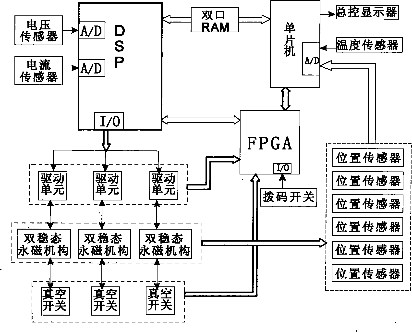
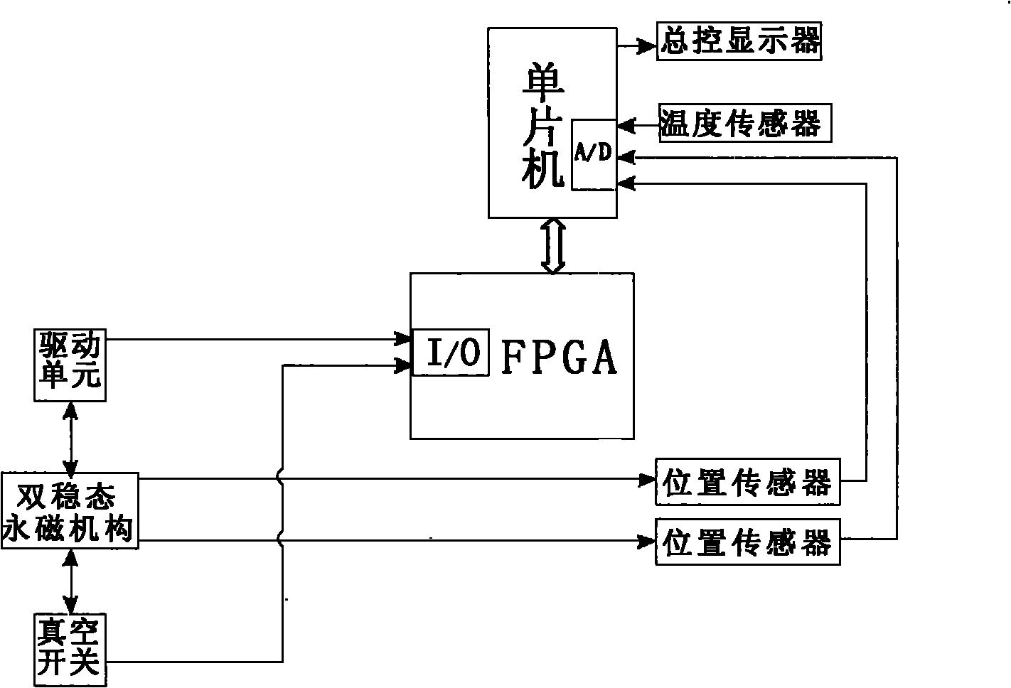
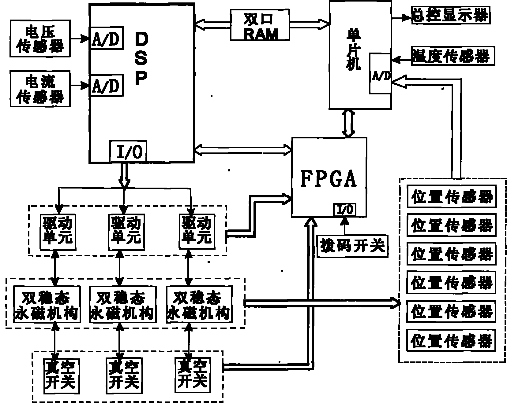
[0027] Example: see figure 1 , figure 2 , the present invention includes a controller, a master control display, a voltage sensor, a current sensor, a drive unit, an actuator and a vacuum switch, and the drive unit, the actuator and the vacuum switch are serially connected in series to form a set of controlled controls,

[0028] It also includes a temperature sensor, the controlled units are three groups, and the actuator is a bistable permanent magnet mechanism, and there are two position sensors on the driving mechanism of any bistable permanent magnet mechanism, and the bistable permanent magnet The mechanism is a very stable electromagnetic drive mechanism, which has few mechanical components, reliable operation, and very low energy consumption. Its biggest advantage is that with the cooperation of a good drive circuit, its motion characteristics are very stable. After thousands of operations, its The parameter drift is small,

[0029] The drive unit adopts a high-preci...


PUM


Abstract

The invention discloses an integrated high-voltage intelligent phase selection permanent-magnetic circuit breaker, which comprises a controller, a master display, a voltage sensor, a current sensor, driving units sequentially connected in series to form a group of controlled elements, an execution mechanism, a vacuum switch and a temperature sensor, wherein three groups of controlled elements areincluded; the execution mechanism is a bi-stable permanent-magnetic mechanism; a driving mechanism of any one of bi-stable permanent-magnetic mechanisms is provided with two position sensors; and thecontroller comprises a single chip, a DSP and an FPGA. The controller, the driving units, the execution unit and the vacuum switch are encapsulated together, so the phase can be automatically detected in the presence of external trigger signals, and the execution mechanism can be driven to accurately and errorlessly switch on or switch off a reactive compensation device at the predetermined phase.

Description

technical field [0001] The invention relates to a circuit breaker, in particular to an integrated high-voltage intelligent phase-selection permanent magnet circuit breaker. Background technique [0002] Capacitor is currently the most common and cheapest device used to compensate reactive power in the power grid. Good compensation can not only stabilize the power supply quality of the power grid, but also save a lot of power loss. In order to follow the changes of the grid parameters, the capacity of the input reactive devices must also change accordingly. At present, the most mature and most used solution is to use switches, such as AC contactors, circuit breakers, electronic switches, etc. to group inputs and Reactive devices are removed, so the reactive power compensation device is mainly composed of the following three parts: reactive power detection and switching controller, switching switch and reactive devices. Due to the special electrical characteristics of reactiv...

Claims


Application Information

Patent Timeline
Patent Type & Authority Applications(China)
IPC IPC(8): H02J3/18H02J13/00H02H3/04
CPCY04S10/20Y02E60/725Y04S10/22Y02E40/30Y02E40/74Y02E40/70Y02E60/00
Inventor 罗文杨明王奔罗飞雪李虎威陈秀敏
Owner SICHUAN PROVINCE SCI CITY JIUXIN SCI & TECH
Why Eureka
Try Eureka