Laser welding connection method of automobile drive axle differential housing and driven bevel gear
A technology of laser welding and differential gear, which is applied in laser welding equipment, welding equipment, metal processing equipment, etc., can solve the problems of reduction, simplification of unfavorable structure design, cost, and complicated manufacturing and processing, so as to reduce production cost, The effect of small deformation and weight reduction
- Summary
- Abstract
- Description
- Claims
- Application Information
AI Technical Summary
Problems solved by technology
Method used
Image

Examples
Embodiment 1
[0010] Assemble the differential case of the automobile drive axle with the driven vertebral teeth, and clamp the assembled assembly on the chuck of the tiltable CNC rotary table, so that the weldment can be rotated as required during the welding process to achieve Different welding speeds. He-Ne laser beam is used for laser positioning, and the focused laser beam is transmitted to the welding area for laser welding. The laser incidence mode is radial incidence, and the defocusing distance of the laser beam focus is -3mm~+3mm. During the laser welding process, the output laser power of the laser is 1kW~3kW; the welding speed is 0.5m / min~3m / min; the laser wire filling welding method must be used, and the specific welding wire is fed at a certain speed (0.5m / min~3m) by the wire feeding device. / min) to the welding seam, the diameter of the welding wire is 0.5mm~2mm; the angle between the wire feeding direction and the welding direction is 75°, and the welding wire axis and S 1...
Embodiment 2
[0012] Assemble the differential housing and the driven vertebral teeth, clamp the assembled assembly on the tiltable CNC workbench, and make the weldment rotate as required during the welding process to achieve different welding speeds. Laser positioning is performed using a He-Ne laser beam so that the laser beam can be delivered to the welding area. The incident mode of the laser is axially incident, and the distance between the incident point and the axis is 90mm to 100mm. Focus defocus of laser beam is -3mm~+3mm; laser power used in welding is 4kW~8kW; welding speed is 1m / min~4m / min; laser wire filling welding is used, wire feeding speed is 1m / min~4m / min, the diameter of the welding wire used is 0.5mm~2mm; the angle between the wire feeding direction and the welding direction is 125°, and the welding wire axis and S 2 Plane angle γ=0°, and S 1 Plane angle 0°1 ≤2mm, distance from laser beam focus -3mm≤L 2 ≤3mm. During the welding process, one or several gases in nitro...
Embodiment 3
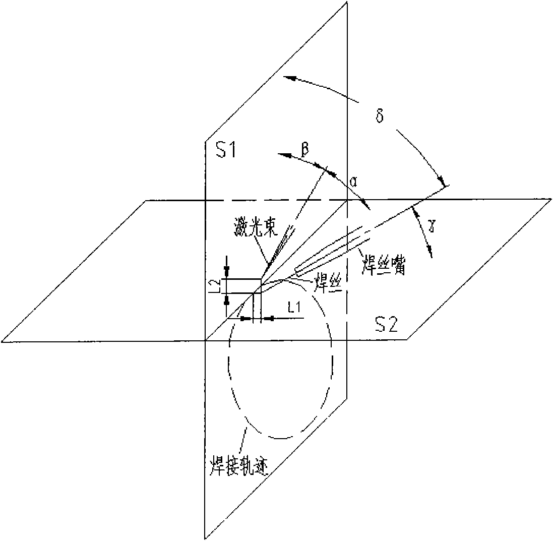
[0014] like figure 1 As shown, the dotted circle is the welding trajectory line, and its plane is S 1 , tangent to the welding trajectory and perpendicular to S 1 The plane of S 2 . The focused laser beam axis and S 2 The angle between the plane is α, and S 1 The angle between the planes is β. Similarly, wire axis and S 2 The included angle of the plane is γ, and S 1 The angle between the planes is δ. The distance from the end of the welding wire to the centerline of the weld is L 1 , the distance from the focal point of the laser beam is L 2 .
[0015] Assemble the differential housing and the driven vertebral teeth, and then clamp them on the tiltable CNC workbench, so that the weldment can be rotated as required during the welding process to achieve different welding speeds. Laser positioning is performed using a He-Ne laser beam so that the laser beam can be delivered to the welding area. The laser incidence method adopts oblique incidence, and the focus defocu...
PUM
| Property | Measurement | Unit |
|---|---|---|
| Diameter | aaaaa | aaaaa |
Abstract
Description
Claims
Application Information
 - Generate Ideas
- Intellectual Property
- Life Sciences
- Materials
- Tech Scout
- Unparalleled Data Quality
- Higher Quality Content
- 60% Fewer Hallucinations
Browse by: Latest US Patents, China's latest patents, Technical Efficacy Thesaurus, Application Domain, Technology Topic, Popular Technical Reports.
© 2025 PatSnap. All rights reserved.Legal|Privacy policy|Modern Slavery Act Transparency Statement|Sitemap|About US| Contact US: help@patsnap.com