Method of treating proppants and fractures in-situ with fluorinated silane

A technology of fluorinated silane and proppant, which is applied in the field of fracturing underground geological formations containing hydrocarbons, and can solve the problems of increasing density, adverse effects, etc.

Inactive Publication Date: 2010-11-17
3M INNOVATIVE PROPERTIES CO
View PDF18 Cites 2 Cited by
  • Summary
  • Abstract
  • Description
  • Claims
  • Application Information

AI Technical Summary

Problems solved by technology

[0002] Also, for example, if a relatively lightweight, porous crystalline ceramic (e.g., alumina) proppant is used, fluids (e.g., fracturing fluids) can penetrate into the proppant, increasing its density, which in turn may affect the Adverse effects of proppant flow into the frac zone

Method used


Image

  • Method of treating proppants and fractures in-situ with fluorinated silane
  • Method of treating proppants and fractures in-situ with fluorinated silane
  • Method of treating proppants and fractures in-situ with fluorinated silane

Examples


preparation example Construction

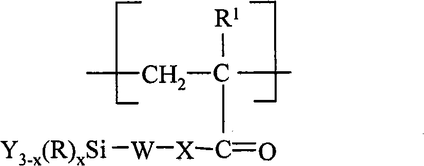
[0151] Usable fluorine-containing urethane oligomers can be prepared, for example, by reacting at least one polyfunctional isocyanate with at least one polyol and subsequently reacting the resulting oligomer with at least one fluorinated monoalcohol and At least one silane reacts. Exemplary reaction conditions, polyfunctional isocyanates, fluorochemicals, fluoromonoalcohols, silanes, and water solubilizing compounds are described in US Patent No. 6,646,088 (Fan et al.).

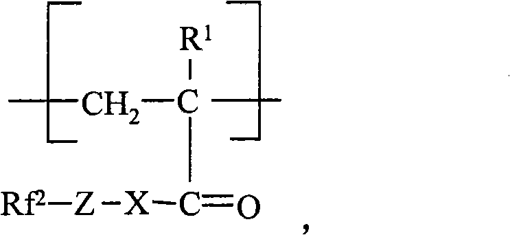
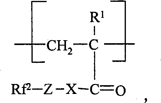
[0152] In the formula -O-Z-Rf 2 In some examples represented, Rf 2 is the monovalent perfluoroalkyl group described above for Rf in the examples of compounds represented by formula I.

[0153] Formula-O-Z-Rf 2 The divalent organic linker Z in can be a linear, branched or cyclic structure, which can be saturated or unsaturated and optionally contains one or more hetero compounds selected from sulfur, oxygen and nitrogen atoms, and / or optionally contain one or more functional groups selected from ester, ami...


PUM

PropertyMeasurementUnit
particle sizeaaaaaaaaaa

Abstract

Method of treating proppant particles present in a fractured subterranean geological formation comprising hydrocarbons in-situ with fluorinated silane.

Description

Background technique [0001] Oil and natural gas can be produced from wells that have porous and permeable formations. The porosity of a formation allows the formation to store oil and gas, and the permeability of the formation allows the passage of oil or natural gas fluids through the formation. The permeability of the formation is necessary to allow oil and gas to flow to a location where it can be pumped from the well. Sometimes formations that hold gas or oil are not permeable enough for ideal oil and gas recovery. In other cases, during operation of the well, the permeability of the formation decreases to such an extent that further recovery becomes uneconomical. In such cases, the formation is typically fractured and the fractures are propped in the open with a propping material or proppant. This fracturing is usually accomplished using hydraulic pressure. Support materials or proppants are typically particulate materials such as sand and (artificially) processed pro...

Claims


Application Information

Patent Timeline
Patent Type & Authority Applications(China)
IPC IPC(8): C09K8/68C09K8/80
CPCC08G18/2885C09K8/68C09K8/80C08G18/289
Inventor 约翰·D·斯基尔德姆小吉米·R·巴兰韦恩·W·凡马德琳·P·申巴赫
Owner 3M INNOVATIVE PROPERTIES CO
Why Eureka
Try Eureka