Exhaust gas analyzer and probe unit

A detection unit and analysis device technology, which is applied in the field of detection units, can solve problems such as inability to supply calibration gas, complicated sensor bracket structure, and increased consumption of calibration gas.

A detection unit and analysis device technology, which is applied in the field of detection units, can solve problems such as inability to supply calibration gas, complicated sensor bracket structure, and increased consumption of calibration gas.

CN101900702AInactive Publication Date: 2010-12-01HORIBA LTD

Image

  • Exhaust gas analyzer and probe unit
  • Exhaust gas analyzer and probe unit
  • Exhaust gas analyzer and probe unit

Examples


Embodiment Construction

[0039] Next, an embodiment of an exhaust gas analysis device according to the present invention will be described with reference to the drawings.

[0040]

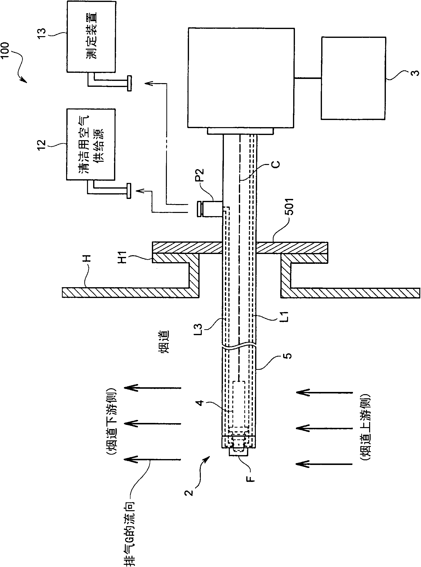
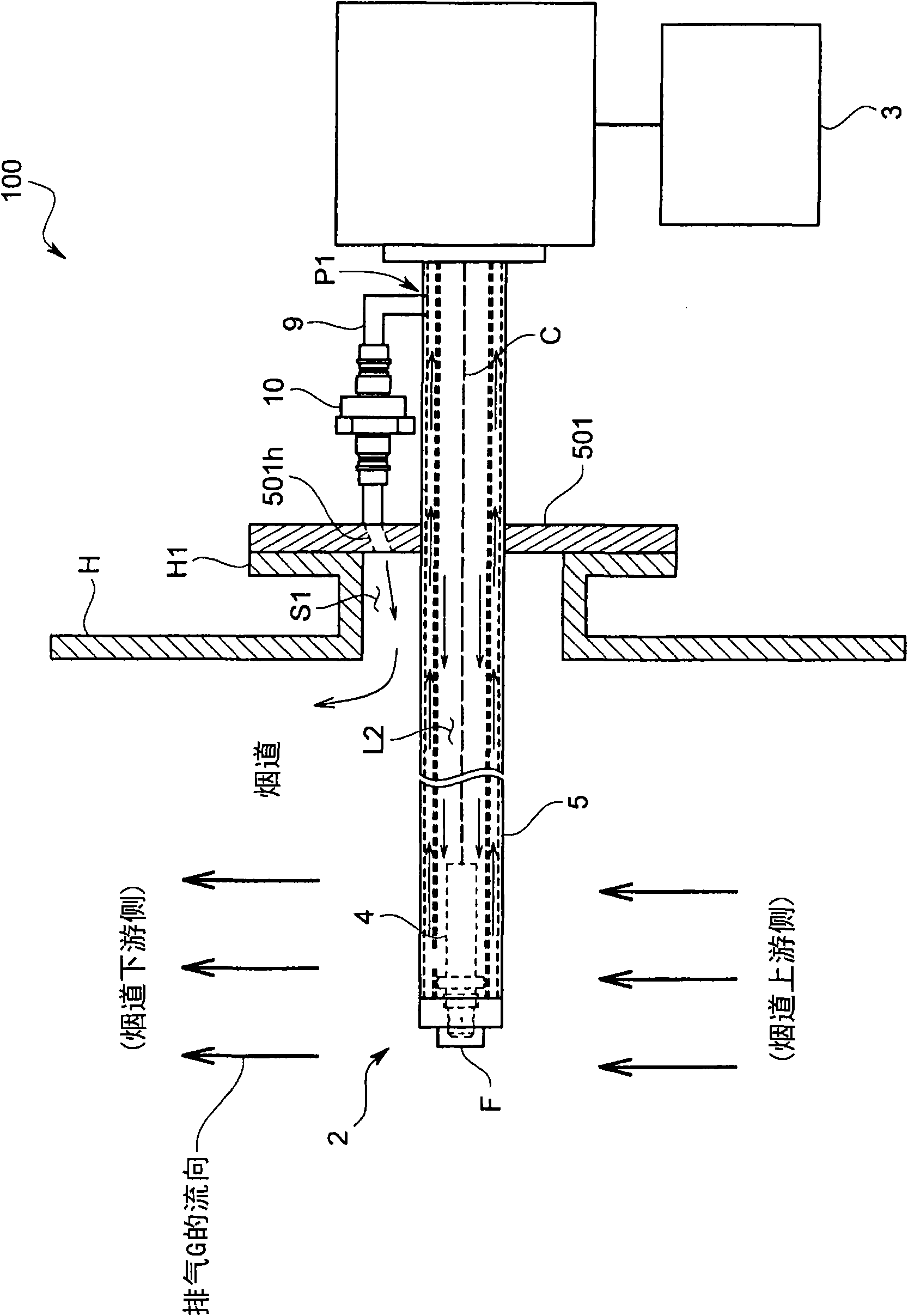
[0041] The exhaust gas analysis device 100 according to the present embodiment is for the exhaust gas G flowing through the flue in the exhaust pipe H connected to a boiler such as a lime incinerator or a heavy oil incinerator, or an internal combustion engine such as a steam engine or a ship engine. The specified components contained (such as NOx, SOx, CO 2 , CO, etc.) is a direct insertion type exhaust gas analyzer for analysis. In addition, the analysis results obtained by using the exhaust gas analysis device 100 (such as the concentration of specified components) can be used for control of denitrification or desulfurization, and the like.

[0042] Such as figure 1 and figure 2 As shown, this device specifically includes: a detection unit 2, which is fixed on the exhaust pipe H, so that its top end is protruded i...


PUM


Abstract

The invention relates to an exhaust gas analyzer and a probe unit. The probe unit has a simple and an easily-assembled structure and reliably guides the correction gas into a whole gas guide hole. The probe unit includes a gas sensor having multiple gas introduction bores for introducing a gas into an inside of the gas sensor, and a sensor holder inside of which the gas sensor is held and that is arranged inside of a duct so as to introduce an exhaust gas flowing in the duct into the gas sensor. A calibration gas flow channel is arranged in the sensor holder and has an opening at an inner surface of a side wall, surrounding the gas introduction bores of the gas sensor, of the sensor holder so as to supply a calibration gas to the gas sensor. A guide groove is arranged continuous to the opening of the calibration gas flow channel and arranged on the inner surface of the side wall along an arranging direction of the multiple gas introduction bores to face the multiple gas introduction bores.

Description

technical field [0001] The present invention relates to an exhaust gas analysis device installed on exhaust pipes of combustion devices such as engines, boilers, waste combustion furnaces, industrial furnaces, etc., for which exhaust Analyze the specified components contained in the exhaust gas flowing through the flue in the pipe. Background technique [0002] Conventionally, as an exhaust gas analysis device for detecting and analyzing predetermined components such as oxygen and nitrogen oxides contained in the exhaust gas in the flue, as shown in Patent Document 1 and Patent Document 2, there are devices as follows: Installed directly into the flue, the exhaust gas is sampled by this detection unit, and specified components such as oxygen or nitrogen oxides in the exhaust gas are detected. [0003] This detection unit specifically includes: a gas sensor, which has a plurality of gas introduction holes for introducing gas into the interior; The exhaust gas flowing in the...

Claims


Application Information

Patent Timeline
01 Dec 2010
Publication
CN101900702A
IPC
G01N27/409; G01N1/22
CPC
G01N33/0006
Inventors
外村繁幸