
Acceleration sensor element and acceleration sensor having same

An acceleration sensor, acceleration technology, applied in the direction of measurement of acceleration, multi-dimensional acceleration measurement, speed/acceleration/impact measurement, etc., can solve the problems of contact between supporting substrate or cover body, increasing influence, easy bending and deformation, etc., to reduce the gap, The effect of reducing stress and improving impact strength

Inactive Publication Date: 2010-12-01
TOREX SEMICON LTD
View PDF8 Cites 12 Cited by
  • Summary
  • Abstract
  • Description
  • Claims
  • Application Information

AI Technical Summary

Problems solved by technology

[0030] In the acceleration sensor of Patent Document 4, since the inner frame is joined to the support substrate at one point, when the support substrate is bent and deformed, the inner frame is displaced with the joint portion as the base point, and there is a possibility that the inner frame is likely to come into contact with the support substrate or the cover. question
In recent years, customers have strongly requested that the overall thickness of the acceleration sensor be thinned. Therefore, when the support substrate is thinned, it is easy to bend and deform, so the influence of the above-mentioned problems has increased.

Method used


Image

  • Acceleration sensor element and acceleration sensor having same
  • Acceleration sensor element and acceleration sensor having same
  • Acceleration sensor element and acceleration sensor having same

Examples


Embodiment 1

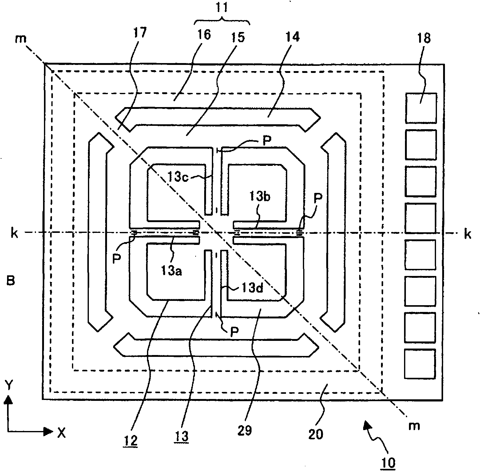
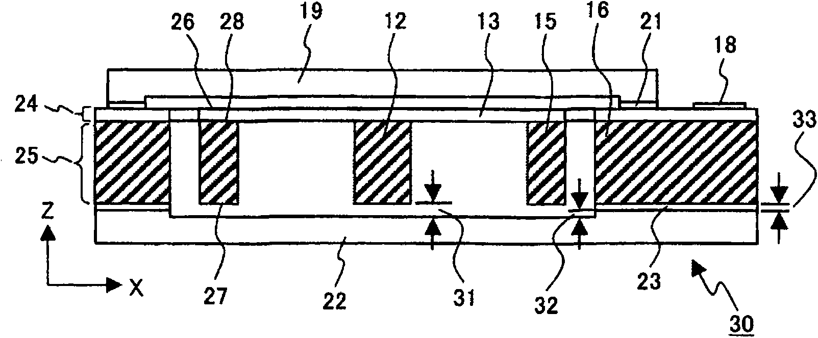
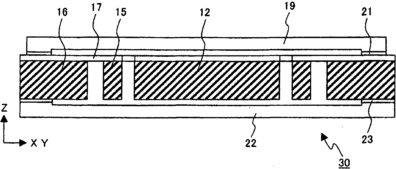
[0064] figure 1 It is a plan view showing the structure of the acceleration sensor element 10 in the acceleration sensor element 30 with a cover of the first embodiment. figure 2 and image 3 is a cross-sectional view of the covered acceleration sensor element 30 of Embodiment 1, figure 2 yes figure 1 The k-k section view of image 3 yes figure 1 The m-m section view of .

[0065] The covered acceleration sensor element 10 of Embodiment 1, for example, can be applied to the prior art example Figure 16 The acceleration sensor and the like assembled into a protective package made of resin are shown. Therefore, in Embodiment 1, a detailed description will be given centering on the acceleration sensor element 30 with a cover.

[0066]

[0067] In the acceleration sensor element 10 of the first embodiment, the weight part 12 is supported from four directions in the support frame part 11 by the four beam parts 13 having flexibility. The support frame portion 11 is se...

Embodiment 2

[0089] Figure 5 It is a schematic plan view showing the structure of the acceleration sensor element 10 of the second embodiment. In the center of the beam portion 13, a shape is formed in which an annular portion 51 is provided as a compressive stress absorbing portion. The silicon oxide film or the like formed on the surface of the acceleration sensor element 10 has a thermal expansion coefficient smaller than that of silicon, and since the film is formed and annealed at a high temperature of, for example, about 950° C., heat is generated when it is cooled to normal temperature. stress. The weight part 12 and the inner frame 15 are formed from the first layer 24 to the second layer 25. Since the thickness of the second layer 25 is thick, it basically contracts with the thermal expansion coefficient of silicon. It is composed of 24 layers, so the ratio of silicon oxide film is high, and the thermal shrinkage becomes small. Therefore, the beam portion 13 is compressed betw...

Embodiment 3

[0095] Figure 6 It is a schematic plan view showing the structure of the acceleration sensor element 10 of the third embodiment. A shape in which an annular portion 52 is provided as a compressive stress absorbing portion is formed on the inner frame support portion 17 . As in Example 2, there is an effect of preventing buckling of the inner frame support portion 17 . When the inner frame support portion 17 buckles, the inner frame 15 is displaced to approach the upper cover 19 or the lower cover 22 , so it is difficult to narrow the gap 31 . Buckling can be prevented by forming the ring portion 52 on the inner frame support portion 17 . In addition, there is an effect of absorbing the influence of the deformation of the outer frame 16, and it is more difficult to change the output.


PUM

PropertyMeasurementUnit
Thicknessaaaaaaaaaa

Abstract

The invention provides an acceleration sensor which does not easily change relative to the external force output and compromises the high sensitivity and impact resistance. A covered acceleration sensor element includes a weight portion, a support frame portion surrounding the weight portion, a plurality of flexible beam portions for connecting the weight portion to the support frame portion to support the weight portion, piezoresistance elements provided on the beam portions, and wirings for connecting them. An upper cover and a lower cover enclosing the periphery of the weight portion together with the support frame portion are joined to the face and back of the support frame portion. Acceleration in the directions of three axes, i.e., a first axis in the joining thickness direction, a second axis in a plane perpendicular to the first axis, and a third axis in the plane and perpendicular to the second axis, or acceleration in the direction of any of the axes, is detected from changes in the resistances of the piezoresistance elements. The support frame portion is separated by separation grooves into an inner frame and an outer frame. The upper cover and the lower cover are joined to the outer frame. The inner frame is connected to the outer frame by a plurality of inner frame support portions having flexibility. The beam portions are connected to both sides of the weight portion along the second axis and the third axis. The inner frame support portions are connected to both sides of the inner frame in a direction in which they are rotated nearly 45 degrees from the second axis and the third axis.

Description

technical field [0001] The present invention relates to a semiconductor acceleration sensor used for acceleration detection of automobiles, aircraft, portable terminal equipment, toys and the like. Background technique [0002] Acceleration sensors are often used as airbag action sensors in automobiles to detect the impact of a car collision as acceleration. In automobiles, it is sufficient to have a single-axis or dual-axis detection function for measuring the acceleration of the X-axis and Y-axis. In addition, the measured acceleration is very large. Recently, acceleration sensors are increasingly used in portable terminal devices and robots, etc., and in order to detect spatial motion, a three-axis acceleration sensor that measures the acceleration of the X, Y, and Z axes is required. In addition, in order to detect minute accelerations, high-resolution and compact acceleration sensors are required. [0003] Most acceleration sensors use a structure that converts the m...

Claims


Application Information

Patent Timeline
IPC IPC(8): G01P15/12G01P15/08G01P15/18H01L29/84
CPCG01P15/0802G01P15/123G01P15/18G01P1/023
Inventor 风间敦斋藤正胜冈田亮二滨口康博
Owner TOREX SEMICON LTD
Learn More