Liquid parallel flow composite tower

A composite column and liquid technology, which is applied in the preparation of hydroxyl compounds, organic compounds, organic chemistry, etc., can solve the problem of lower separation efficiency and reflux ratio of parallel flow trays, problems of equipment and technical economy, and inability to fully display separation efficiency, etc. problems, to achieve the effect of reducing the diameter of the tower body, increasing the effective mass transfer area, and improving the mass transfer efficiency

Active Publication Date: 2012-02-15
SHIJIAZHUANG GONGDA CHEM EQUIP
View PDF0 Cites 0 Cited by
  • Summary
  • Abstract
  • Description
  • Claims
  • Application Information

AI Technical Summary

Problems solved by technology

In 1981, Jenkins first proposed the parallel flow tower structure of Parastillation, and conducted experimental research on it. Under the same separation requirements, the separation efficiency of the parallel flow tray was greatly improved, and the required reflux ratio was also greatly reduced; later generations The column type has been further studied and improved, and the result proves that the co-flow structure can significantly promote the improvement of the tray efficiency of the rectification column, but due to the problems of equipment and technical economy, this type of tray has not been seen so far. reports on industrialization
The Slit tray proposed by Kuhni Company is a direct industrial implementation of the Lewis co-flow effect, which can effectively eliminate the liquid stagnation area of ​​the conventional cross-flow tray and increase the bubbling area of ​​the tray, so as to ensure the mass transfer and separation effect. The production and processing capacity is greatly improved, but the tray adopts liquid phase continuous (bubbling) operation, and the mass transfer area is limited to the liquid layer on the tray, which cannot fully demonstrate the advantages of the co-flow effect to greatly improve the separation efficiency

Method used


Image

  • Liquid parallel flow composite tower
  • Liquid parallel flow composite tower
  • Liquid parallel flow composite tower

Examples


Embodiment Construction

[0023] The present invention will be described in further detail below in conjunction with the accompanying drawings and specific embodiments.

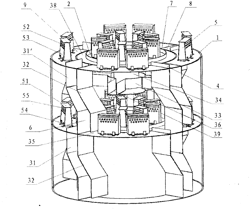
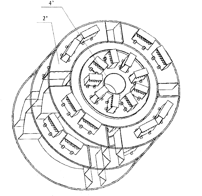
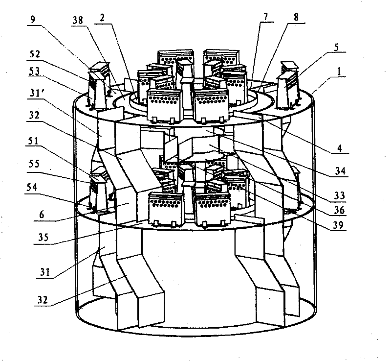
[0024] figure 1 It is a liquid co-current composite tower, including a cylindrical tower body 1 and a multi-layer continuous mass transfer tray arranged in the tower body 1. The tower body is divided into a cylindrical inner tower 8 and an annular outer tower 9, and the inner tower is set outside In the tower, the tray I 2 in the inner tower corresponds to the cross-section of the inner tower and is arranged in parallel, and the ring-shaped tower II 2' corresponding to the cross-section of the outer tower is also arranged in parallel in the outer tower; the inner tower and the outer tower are respectively arranged There is a downflow system.

[0025] The downcomer system of the outer tower includes four sets of downcomers arranged alternately around the inside of the outer tower, and the four sets of downcomers divide the entire oute...


PUM


Abstract

The invention relates to a liquid parallel flow composite tower which is gas-liquid contact equipment used in a mass transfer process, a heat transfer process and the like in fields such as chemical industry, oil refining, petrochemical industry, pharmacy, environmental protection and the like. The composite tower comprises a tower body, wherein the tower body consists of an inner tower and an outer tower; the inner tower is sleeved in the outer tower; tower plates corresponding to cross sections of the tower body are arranged in the inner tower and the outer tower respectively; and each tower plate is provided with a down-flow system which can allow liquid on each layer of tower plates to flow in the same direction. The composite tower has the advantages of realizing large-flux mass transfer of liquid, preventing a stagnation zone from being formed on the tower plate, increasing an effective mass transfer area, enhancing treating capability, enhancing gas-liquid mass transfer averagedriving force on the tower plate and further improving the mass transfer efficiency of the tower plate.

Description

technical field [0001] The invention relates to a gas-liquid contact device, in particular to a liquid co-current tower commonly used in mass transfer, heat transfer and other processes in chemical industry, oil refining, petrochemical, pharmaceutical, environmental protection and other fields. Background technique [0002] At present, the gas-liquid contact equipment used in the mass transfer (such as rectification, absorption, desorption, gas stripping and other unit operations) and heat transfer in the fields of petroleum, chemical industry, pharmaceuticals, environmental protection, etc. Tray towers are based on liquid-phase continuous trays such as sieve tray, float valve, and bubble cap types. Multi-layer trays are arranged in a cylindrical tower body, and some mass transfer elements are also arranged on the trays. Some newly developed trays are also improved forms of these trays. These trays have small processing capacity, low tray efficiency, large pressure drop, and...

Claims


Application Information

Patent Timeline
Patent Type & Authority Patents(China)
IPC IPC(8): B01D3/18B01D53/18C07C29/82
Inventor 张继军
Owner SHIJIAZHUANG GONGDA CHEM EQUIP
Why Eureka
Try Eureka